It may or may not be apparent that we spend a considerable amount of time away in the camper. I would estimate that we are away two months of the year, if not more, and since fitting solar over two years ago ( documented here) , it has made the time in the van a lot more flexible. We seldom used electric hook up (EHU), and this has saved us enough cash to pay for the original installation with money to spare. However, after some unreliability cause as a result of the original batteries failing in the last few weeks, its time to make some decisions about where we go next.
I have been really happy with the original install, and if we had not had any issues I am sure we would have just carried on the way we have been. The limited size of the battery compartment behind the front seats means battery options are very limited. On top of this, any battery that will fit the aperture was never really designed to provide consistent power to devices like fridges etc during lengthy periods away. The more I researched it the more convinced I was that the original leisure batteries could only really last a couple of years in my configuration. Deep cycle batteries are designed for continual usage of persistant charge and drain, but these are always going to be higher, if not longer or wider than the stock compartment would ever allow. So with this in mind, if I was going to push forward with my next generation solar solution, it was inevitable that the batteries were going to have to me stored elsewhere.
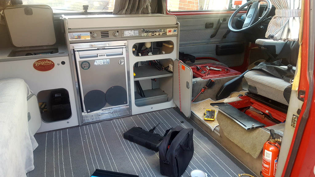
Once I got my head round this I felt like my hands had been untied! I started stripping out the contents of the cupboards so I could really get to grips with the space I had available. I soon decided that the small lower cupboard next to the fridge was probably the most suitable location for the batteries, and the cupboard above that would be for the fuse box.
Cupboard chosen for batteries is lower left of this photo.
The small lower cupboard had a divider panel in which essentially separated the storage side from some of the consumer electrics ( RCD breaker switch, power socket and EHU and associated cabling and junction box ), so this needed to come out to free up some space.
This is a photo of the lower cupboard with the divider removed. The battery is just for reference.
It soon became apparent that the RCD and some of the cabling would also have to relocated if I wanted to run a two battery setup. Once the cupboard was clear enough to get some measurements we looked online for the largest AGM battery that would fit the space and ordered it.
AGM Leisure, Power Plus Type 120 battery
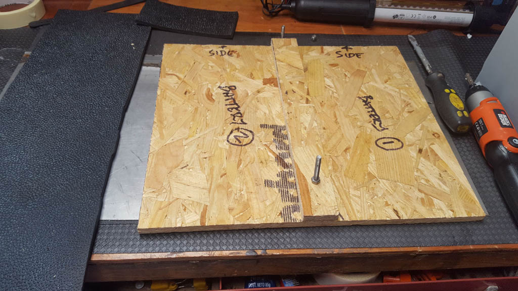
So I set to fabricating the base plate for the batteries out of a sheet of OSB I had lying around.
I wanted to do the whole install as sympathetically as possible, so drilling holes or applying fixings to anything that was an original component of the van would only be done as a last resort. Making a base plate for the batteries gave me an element of flexibility to be able to use this as a fixing platform for securing the batteries in place. It was cut just big enough to snugly fit in the base of the lower cupboard. From a previous project I had an excessive amount of thick black rubber matting, so I decided to place this on each side to create a non slip base.
battery base plate in location complete with rubber matting
This picture shows both the lower cupboard divider and the upper shelf which are going to be put into storage in a safe place in case the process needs to be reversed.
Left is lower cupboard divider. Right upper cupboard shelf which forms the cupboard base.
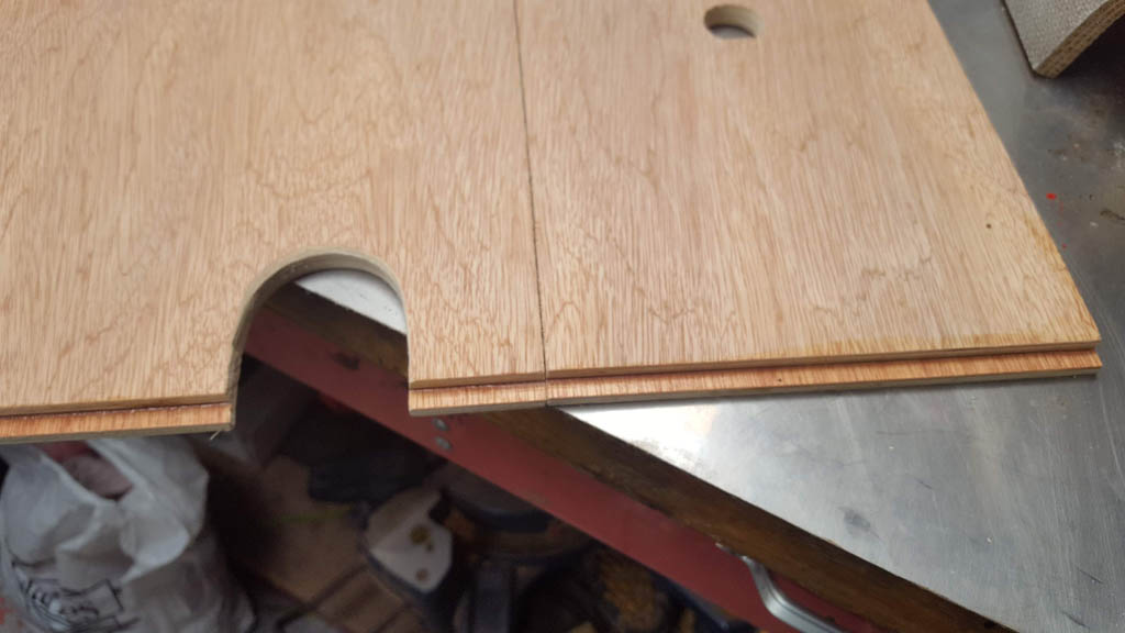
Due to the fact the lower cupboard is going to be filled with batteries, and the installation of them can only be achieved effectively with access via the upper cupboard, placing the shelf back into its location afterwards will not be achievable in one piece. In one piece the shelf has to be dropped in at an angle to the lower cupboard space and juggled up into position. On top of this It will need an additional hole cutting in the shelf to allow access for cabling. So this is my reason for fabricating a new shelf.
I chose to use 5mm plywood. This needed cutting to shape and bonding one on top of the other. Reason for not using 10mm in the first place is that I needed to create a lip that forms a resting point along one edge.
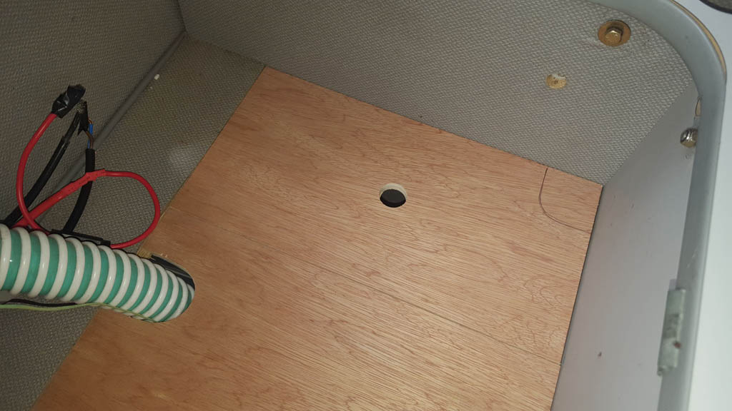
Here it can be seen in place.
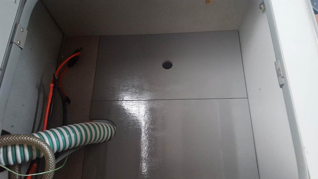
And here after the cut is applied and the components are painted.
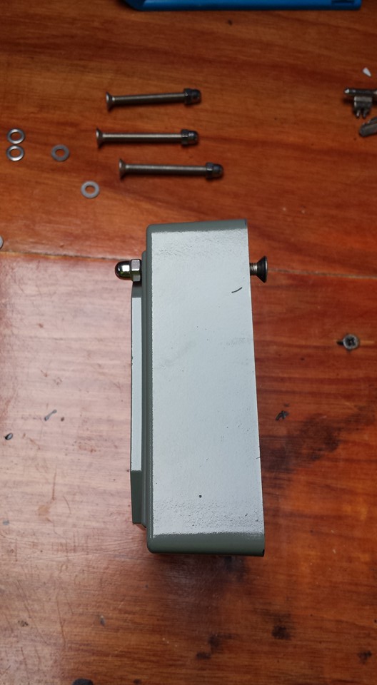
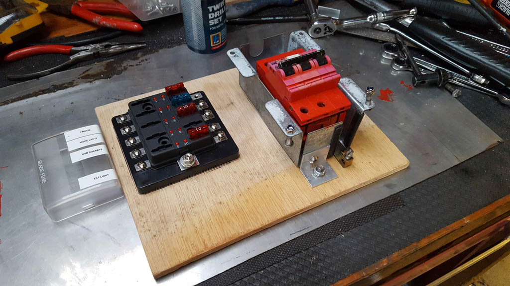
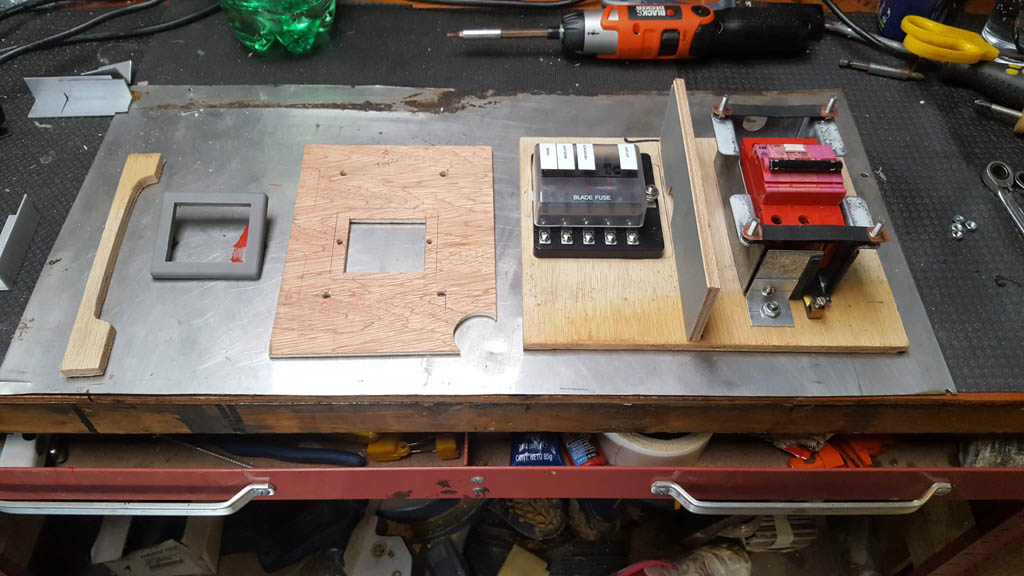
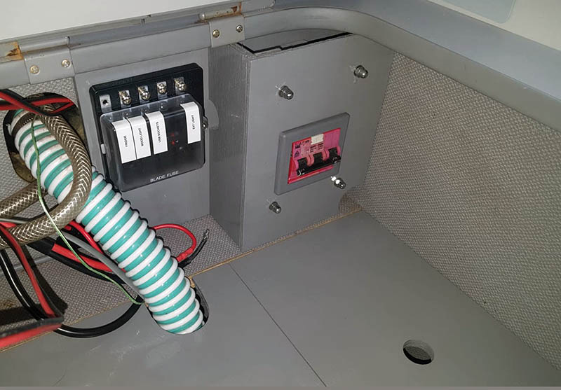
Next is the relocation of the RCD and fuse box. I used a piece of 8mm plywood board cut to size for the back plate. I used two stainless M8 bolts to act as fixings for the RCD onto the back plane. The fuse box uses two self tapping screws.
After some head scratching i fabricated the rest of the components to build up the casing for the RCD unit.
These were then painted in grey enamel to match the cupboard base.
It can be seen here offered into location. Still some way to go yet though.
So I have the new battery and have pretty much fleshed out locations for all of the components in my system. The original live wiring that goes to the old leisure battery location will need feeding back to the new battery location in the lower cupboard and connected to the battery.
My original solar charge controller was a PWM (Pulse Width Modulation) unit. It had feeds for two batteries and came with a LCD display. However, it is fairly basic in its technology and only really acts as a switch filtering power to the batteries when the panels receive sunlight, and stopping drain at night.
During my recent research into solar controllers I have come to the conclusion that I would probably benefit from moving onto the more expensive MPPT (Maximum Power Point Tracking). The MPPT harnesses the solar energy before sending it to the batteries much more effectively. The increase in power to the batteries can be 30% more efficient if figures are to be believed. Along with this efficiency, they seem to have a lot more intelligence and diagnostics available to draw from this type of solar controller. Monitoring using a smartphone via the installed application gives lots of analytics.
So in the next few days I will be placing an order for the above Victron Energy 100/20 , 20 amp solar charge controller with built in Bluetooth. This can be monitored by a phone app when within Bluetooth range. This will be positioned in the original leisure battery location behind the drivers seat. So I am looking forward to getting the rest of wiring completed ready for our two week break in September. On that note I will conclude for now by saying I will add more to this particular BLOG post as I move forward with the rest of the install to hopefully provide complete a guide to anybody that may be considering going down a similar route.
A little progress on the gearbox…Due to issues with a batch of faulty parts, the gearbox wasn’t ready for my September holiday. As has been covered in a previous post we managed to get away thanks to a friend lending me a box. Ironically, I received an email stating my gearbox was ready the first day of our three week break. Suffice to say I was not really in any positing to collect until the end of September where it sat in my garage until a couple of days ago.
The box build spec changed from standard to include a 4.14 final drive, stronger 4 pinion differential and new differential bearings. This should compliment my new, more powerful AAZ engine with longer gears throughout and a higher cruising top speed.
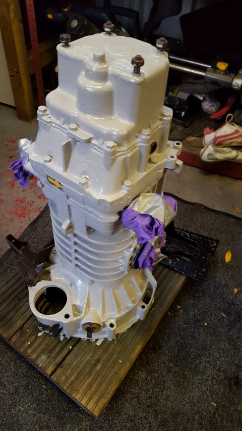
Knowing that the gear boxes are prone to corrosion due to its position underneath the camper in front of the engine, my intention was to paint the casings before fitting the box. I thought about etch primer (the yellow stuff that comes out of an aerosol can), but decided to try Hammerite primer on a small section of the alloy to see how well it adhered. After a couple of days I checked and it seemed to have keyed on really well, so the rest of the box was painted.
I am in no great rush to have the box fitted, and the reality is it’s probably going to sit in my garage for the next 6 month until my van is booked in for a service at Brickwerks. I’ll get them to fit it then 🙂 . Hammerite takes a good few weeks to cure, after which I will paint again with a mid grey engine enamel.
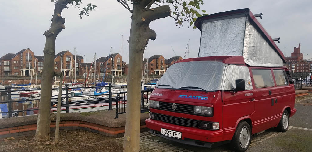
I have had a couple of people ask me about the thermal screens I use on my van (seen above on both the window and pop top). Both of these get used on almost every camp over oblivious to the time of year or temperature for reasons explained below.
The pop top roof canvas was purchased directly from Paucer
The obvious reason for buying the screen initially was to try and retain the heat from inside of the van during cold weather. However, we do find that it reduces the noise slightly if camped in busy locations, along with reducing buffeting sounds when windy, and the sound of rain on the canvas. During summer it reduces the amount of light in the van which can be helpful when the sun starts to rise at 5am. After all, who wants to be woken up at the crack of dawn when your on your hols? 🙂
All T3 / T25s have glass window screens and door glass so a thermal wrap is a must if you want to stand any chance of eliminating condensation from the cab area of your van. The Silver Screen was an expensive purchase in comparison to the alternatives that are on offer from the likes of Just Campers etc. At over £100 it was twice as much, but my purchase is still as good today, as the day I brought it. You can definitely see the difference in the thickness of the quilting and the old saying ‘you get what you pay for’ certainly rings true here. The screen cover was brought directly from Silver Screens ( www.silverscreens.co.uk ).
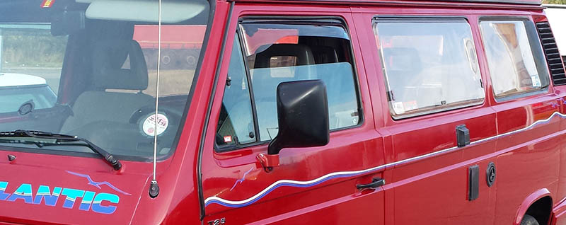
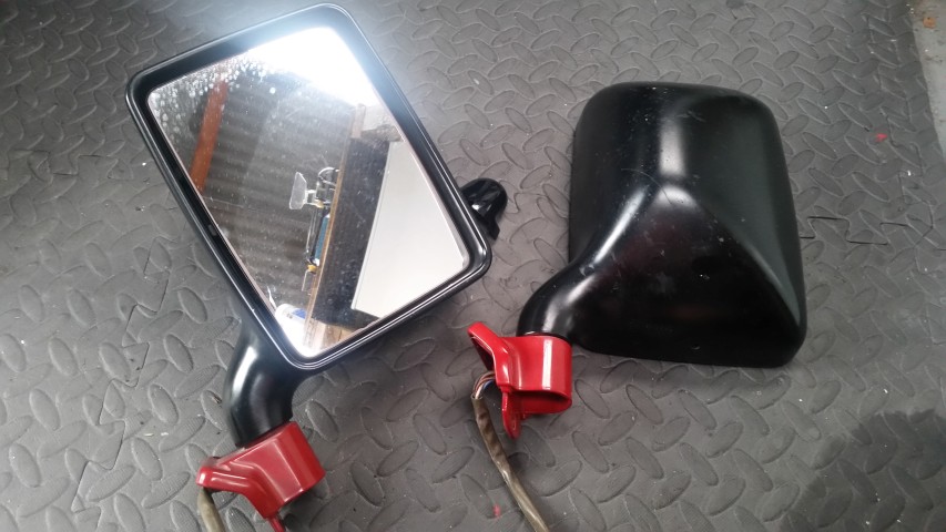
The Atlantic was one of the few vans that came with big mirrors as standard. These were always colour coded from factory in one of three available colours. White, calypso green or red. My van on the other hand came with mat black mirrors.
black mirrors
This didn’t particularly bother me as I always knew I would get round to painting them at some point. It’s just never really been a priority, what with the van getting plenty of use during both winter and summer. However, my current situation means Wolfgang is off the road for the time being, so this became an opportunity….(always need a positive spin with these vans ?)
Unfortunately, its not quite as simple as just unscrewing them via the visible screws on the door bracket. They are heated and servo adjustable from a switch module on the left hand, drivers door. This means that the door cards have to come out on both sides. The fallowing video is a guide to removing the door cards for anybody that may need to perform this process: (courtesy of Van-Again on YouTube)
Below is my door after card removal:
Door card stripped
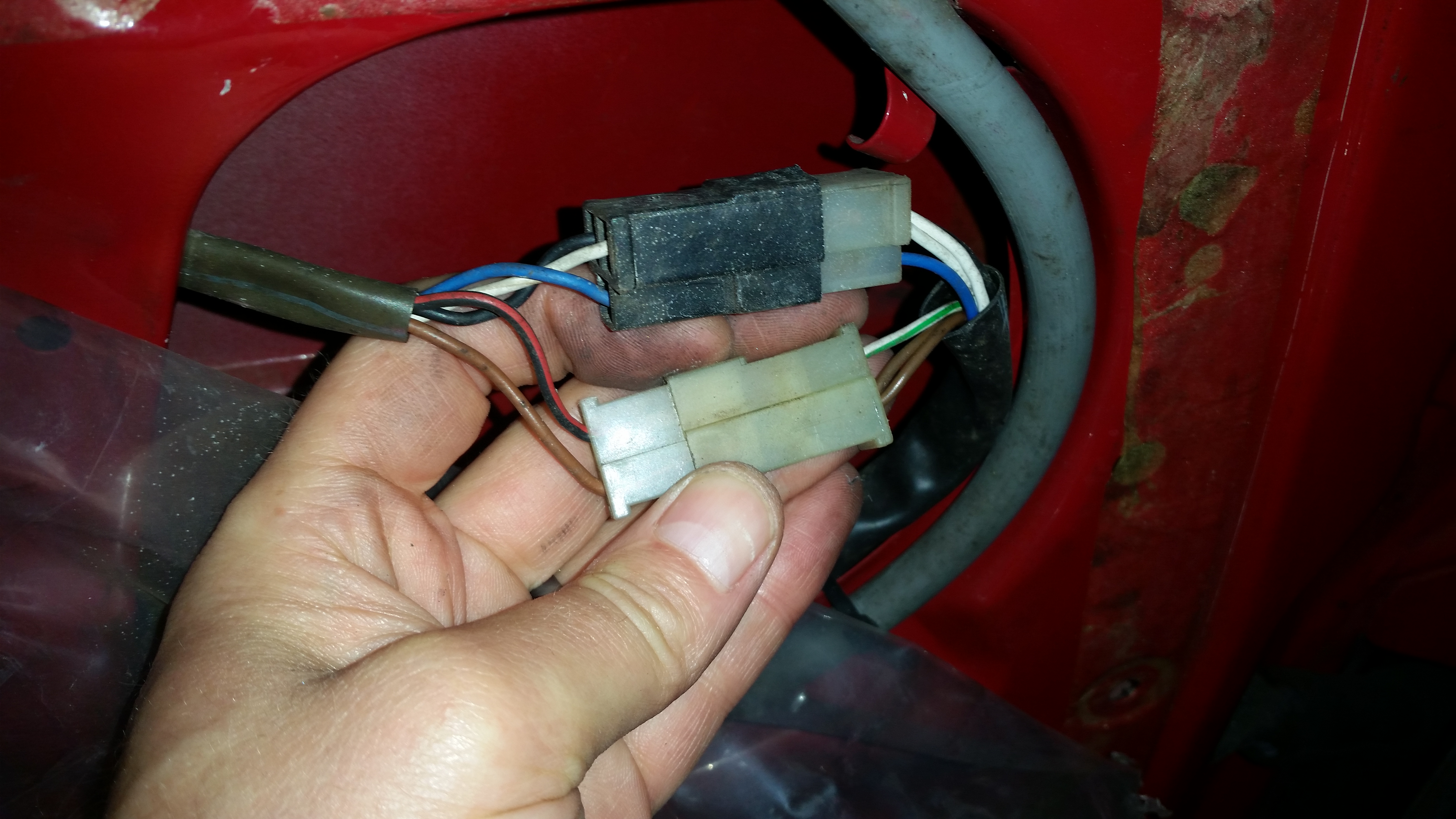
Then electrical ‘block’ connector needs disconnecting and stripping….
Electrical block connector (needs striping)
after which the wires can then be passed through the small cable aperture to mirror.
Cable entry / exit hole in door
Its not massively difficult, but a little more involved than one would first imagine.
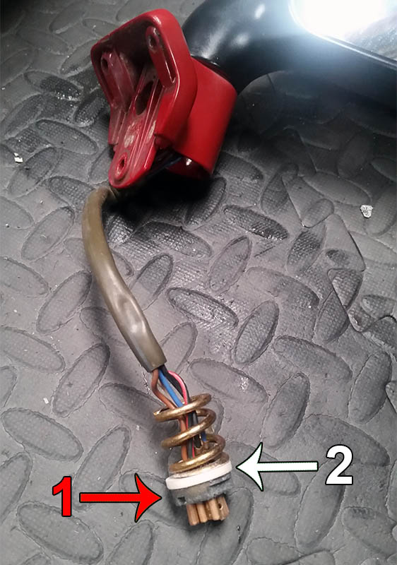
Then the mirrors need stripping into their basic components before paint. Separating the bracket from the mirror was done using a pair of long nosed pliers . There is large slotted nut (1 in below image) that winds up against a perspex bush (2 in below image) and spring. Again, not the easiest thing to do especially if the nut hasn’t been removed for a number of years.
Mirror brackets removed
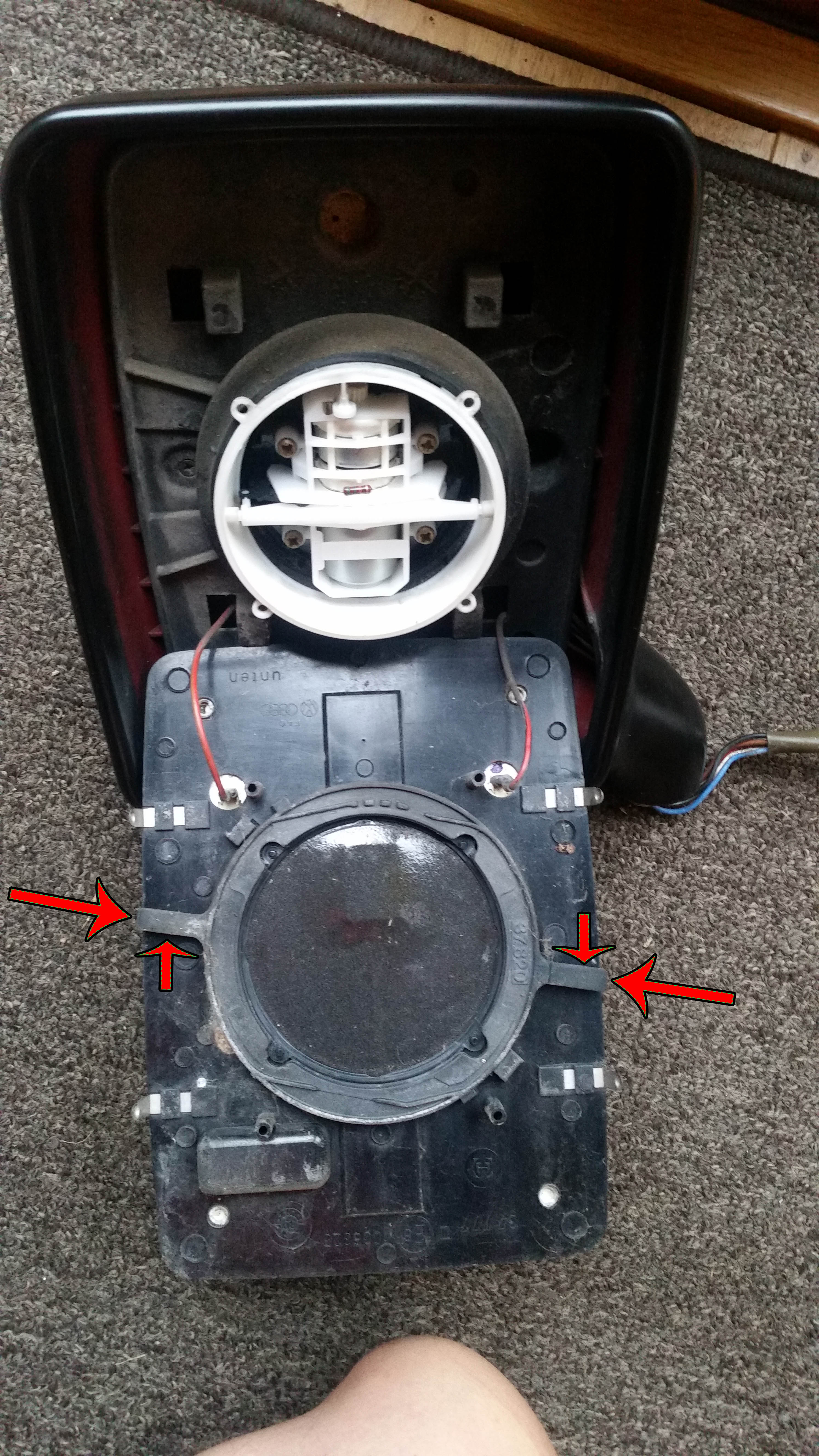
The mirror glass also needs to be removed. If you look closely in between the glass and the outer casing you can just see the two tabs sticking out on either side. Not particularly clear under instruction exactly how these hold the mirror in, but with a couple of knives carefully slotted down the side, and an up movement on one side, and down on the other, the mirror pulls free of the servo unit.
Wires connected to mirror are for heated / defrost function during cold weather
From the picture above I was slightly surprised to see the original colour inside the casing. I did strip one of the mirrors down even further in the hope that I could just send the plastics and bracket away for spraying, but realized the connectors on the end of the loom wouldn’t go through the hole in the bottom of the mirror. This meant they must have been crimped on after they were thread out of the aperture during construction at the factory. I wasn’t willing to cut them off and re connect after paint, so I left the whole servo assembly in the mirror. You can see more clearly the original paint in the photo below.
Original paint in mirror.
I can only assume that the original external paint must have gotten scratched, chipped or dis-couloured to the point where a previous owner decided to take matters into his own hands with a DIY spray-job using a can of mat black paint.
So this was just about as far as I could take it. I was considering getting a few rattle cans made up and having a go at painting them myself. However, these wouldn’t have been cheap, and these on top of the extra wet-n-dry emery paper and primer, would have meant that I probably wouldn’t be saving a great deal against the cost of a professional paint shop. So the paint was purchased and both mirrors and paint were taken to a body shop I had used previously to have my Fiamma Box painted.
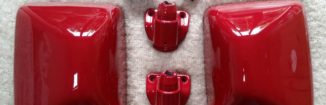
Two Days later I collected and I must admit I am pretty happy with the results . I just need to build them up and pop them back on the van 🙂
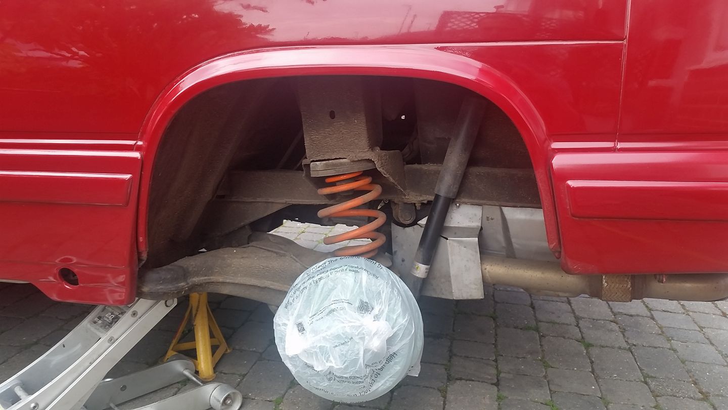
So my van has gearbox issues! But no reason to stop chipping away at the things that have annoyed me until that can be fixed. Basically, the gaps in my wheels aren’t massive because of the style of alloy, but annoying all the same to see the rusty drum behind. So yesterday / today I jacked the van up, popped the wheel off and set to realizing my goal. To paint the drum red.
Anyways, one thing leads to another, and before you know it (5 hours later actually), I’ve washed away all the mud, painted the trailing arms and stone chipped the wheel arch.
The finished article:
The replacement gearbox should arrive on Tuesday, along with new clutch and slave cylinder from Brickwerks (due to be fitted on Friday locally). Nothing like cutting it fine. We should be on the ferry for our Euro trip just over a week later. Lets hope there are no issues with the replacement box!?
Sunday 9th April was a gorgeous sunny day that lent itself perfectly to using the van as a base for a family outing at Calke Abbey. Its quite unique in the location we live in as much as the owners (National Trust) allow you to park on the grass fields surrounded by trees and woodlands which forms the long driveway up to the historic house itself.
Pitched up at Calke
All in all it turned out to be a very busy day, but in the back of my mind i knew that this would be the last trip in the van with the trusty 1.6TD JX engine that had provided us with so many great journeys since ownership. Getting really sentimental, i guess you could say that we were not the only people to benefit from the trusty power plant, so it makes sense to show its penultimate day in a great light.
Pitched up at 9am waiting for family
So we got back from Calke, and proceeded to rid the van of anything that wasn’t appropriate for the journey the following day. No camping equipment required, but lots of new and refurbished parts in readiness for the trip to the garage in sunny Yorkshire.
Monday we were greeted with another fine day weather-wise, but this was all predicted by the met office so no great surprises, but welcome all the same. We left Derby for Honley just after rush hour and arrived at our destination at 10.30am. The visit to Brickwerks has become an annual pilgrimage. This was our third time and with each visit address increasingly more expensive issues to get Wolfgang back to his former glory.
After a brief conversation with Simon and Micheal, Mandy and I tootled off thinking I was just lacking a fuel pump bracket. This didn’t concern me massively. However, by the time we had walked the short distance to the train station, and got on the train to depart home, emails were telling me the list of missing parts were increasing exponentially. My lack of research, and my over simplification of what could and couldn’t be used from the old JX unit left me in a bit of a sticky situation.
Parts required:
Intermediate shaft pulley.
Intermediate shaft flange.
Intermediate shaft pulley bolt and woodruff key.
Brake vacuum pump.
Oil seal housings for both ends of the crank.
Flywheel end – seal
Timing belt rear cover.
Timing belt upper cover.
Timing belt lower cover.
Oil filter head.
Oil cooler.
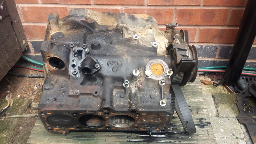
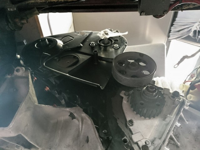
As a recap, I brought a second hand engine from eBay which was similar, but not the same as the engine i needed to put in my van. It was from a later model VW van, and slightly bigger in capacity to the one i had in my van (1900cc) This was an acceptable exchange for the 1.9TD AAZ i needed back from the engine shop. I stripped it back the core engine and sent it away to AW Engineering for checking.
ABL ready to be shipped to engine shop
Feedback was positive for the returned unit, and my new engine (AAZ Code) was returned to me at a later date in a polythene bag. This is where it stayed in its packaging until we arrived at Brickwerks.
My van only had four days allocated by Brickwerks to get the old engine out, and new in. If things over ran it would put them in a sticky situation for there future workload. Mandy and I were looking forward to a little shopping and a meal in Sheffield on the way home, but my mind was now on trying to get the missing parts to the garage. With such an early spanner in the works the day had become a little stressful.
With so many parts required i contacted AW Engineering who provided the engine. I knew they were big with VW engine re manufacturing, so they were a good place to start in terms of providing the sheer quantity of parts i needed to keep things on track. Long story short, after numerous emails and phone calls, AW had accumulated a ‘kit’ of parts required to complete the install. £300 was the sum required to purchase bits and have them shipped to Brickwerks.
The following day images of the progression started to arrive via email.
Turbo spacer required for 1.6 to 1.9cc
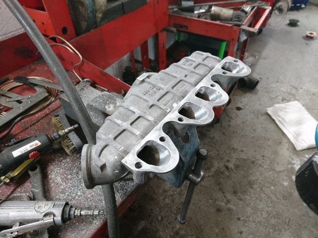
Porting on inlet manifold
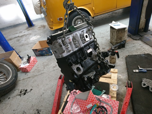
Engine
The engine, manifold and turbo
On Wednesday I had notification that the extra parts had arrived from AW, along with this photo to say that ‘It’s in the hole’ 🙂
In the hole 1
No idea what this is but it looks clean and shiny at the same time 🙂
So that’s where we are at the moment. I’m in a happy place because its really looking fantastic.
The moment I saw one of these fuel filler caps I knew I had to have one. It replaces a very bland component on the van with something that is far more eye catching and appropriate for such a high spec camper.
This was not inexpensive by any stretch of the imagination. Quote Brickwerks website:
“This is not a cheap “stick on” kit, its designed for a T3, and sold exclusively by us in the UK. We wanted a kit that was easy and straightforward to fit using the best design and highest quality parts.”
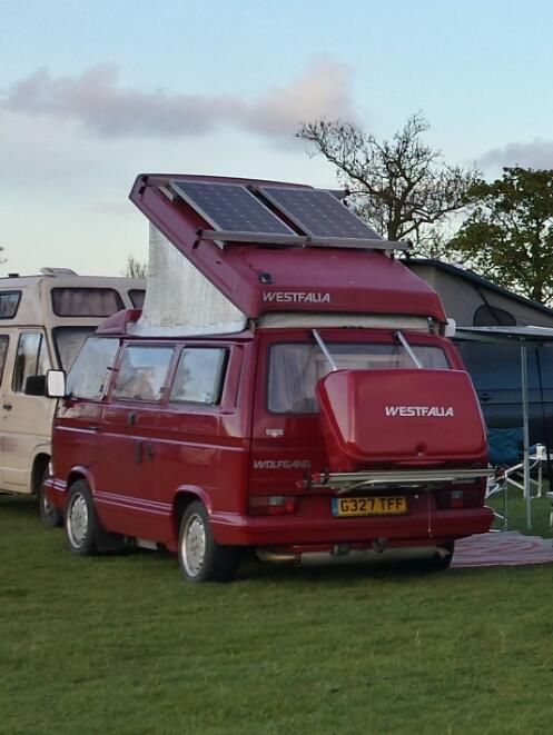
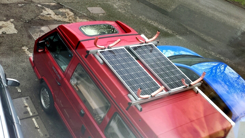
I decided I was going to go down the Solar route late last year because the costings didn’t seem particularly expensive. On top of that I had a mounting solution available already with the Sherpas Combi Translift roof rack system so it was a bit of a no brainer really. I figured that if we can eliminate paying for electric hook-up for one year by running off batteries, we could almost re-coupe the cash spent on all of the components included (approximately £300).
So for my birthday in November I asked for Amazon Vouchers and I got my first panel. I promptly sandwiched it between two of the four sliders on my Combi Translift. This was done using stainless fixings. 🙂
For Christmas i asked for more vouchers and got my second panel plus the Dual Battery Charger Controller and the LCD Monitor.
Dual Battery Charger
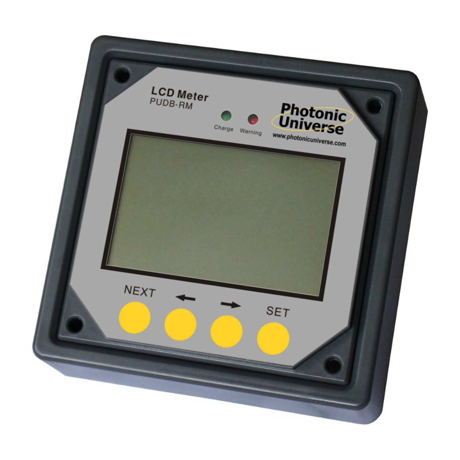
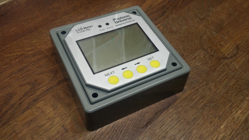
LCD Monitor
So the second panel was fitted…
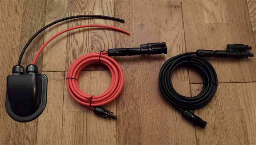
After a great deal of research I decided that the cable for my panels would be fed into the van via a cable entry gland. I found a black one that looked OK on the webpage, but when i received it I was disappointed. It was much larger than i thought and not very aesthetically pleasing. So I ended up getting a second one that was only available in white, but much smaller and less obvious. I plastic primed it and gave it a good few coats of metallic grey paint.
Cable entry gland
The only thing I was lacking now was the cables. I sourced these from eBay along with a pair of adapters that would allow both panels to hook into a single feed.
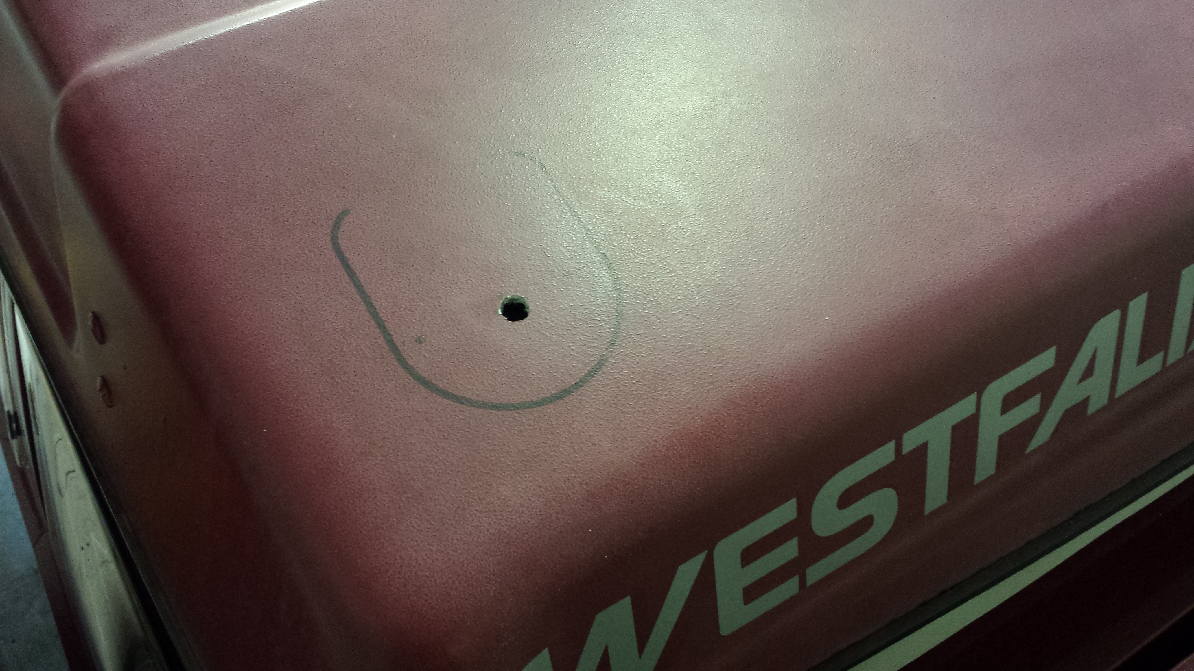
The next stage required drilling a hole in the pop top roof and mounting the cable entry gland with Sikaflex. I don’t make a habit of drilling holes in my van, but the way I looked at it was a hole drilled in the fiberglass pop top was far less intrusive than drilling a hole in the metal bodywork (which was an option I had seen done before). Each one achieves the same objective, and there is nothing to say that one way is right and the other wrong, but this is the route I decided to go down.
So I positioned and marked the gland on the roof for reference. Then drilled the hole.
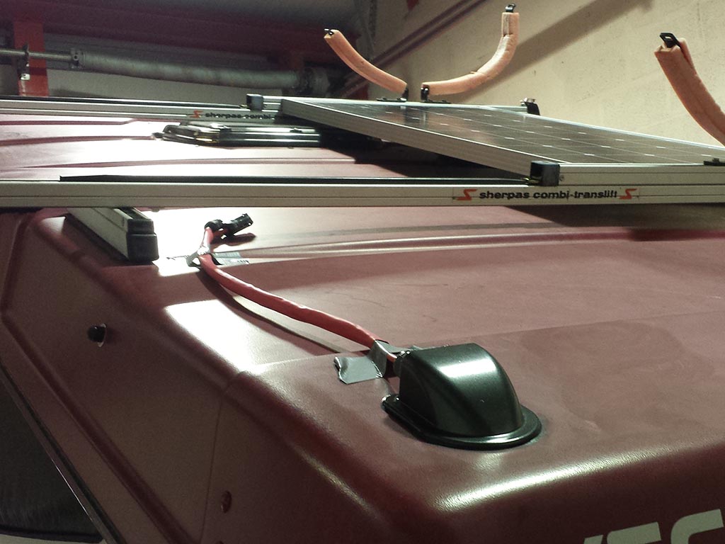
The entry gland was positioned after feeding the cables into the aperture. And Sikaflex was used to bond it to the roof. This was held in position for a couple of hours with tape to allow time for the bonding agent to go off enough that I felt i could remove it.
So the solar cables lay coiled up on the bed in the top bunk for a month or so before i started pushing forward with the internal cabling. First job was to try and establish the best route into the wardrobe. Then drill a hole (eeek!).
Cable held down by cable clips
The cable drops into the top of the wardrobe area initially on the outside in between the rear window curtain. The com’s /data cable was just eased up along the rubber where the wardrobe front and the roof meet and follows the same path the solar cables take into the wardrobe.
Data cable for LCS Display
I made a small nick in the seal where it will rest and feed into the LCD display unit.
The unit itself came in black as pictured previously, so that’s been plastic primed and sprayed ‘industrial grey’ to more closely match the Westy interior.
Once the cables were fed into the wardrobe i needed to create a pathway to the location the solar controller would be sited. Since I decided solar would be a feature on my van I was looking constantly for information on how and where others had sited the components. The solar controller I had seen mounted in a multitude of places. These included
Inside the wardrobe – This would reduce space in an already narrow aperture and get in the way mounted higher up. Lower down this was not an option because this is used for the storage of shoes etc)
Outside the wardrobe underneath the LCD meter – This would look ugly with all of the wires feeding into the controller and would be an unnecessary eyesore (but i have seen it mounted there)
One particular location seemed better than any other. This was in one of the storage compartments next to the fridge underneath the rear table. It was deep enough that the controller would have enough room below it to accept the cables. So confident in my conviction that this was the place of all places, I set to drilling the two holes necessary to feed the cables and reach the unit. One hole was from the wardrobe to the first storage compartment above the water tank.
Feed from inside the wardrobe
Inside the first compartment
Feed into the second compartment next to fridge.
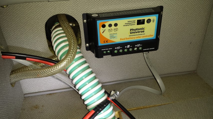
So once the cables were fed into the compartment the next thing was to mount the controller. I first placed the solar controller where i wanted it, marked the holes with a black pen and used a braddle to get the stainless self tappers to bite into the hardboard.
Solar controller mounted.
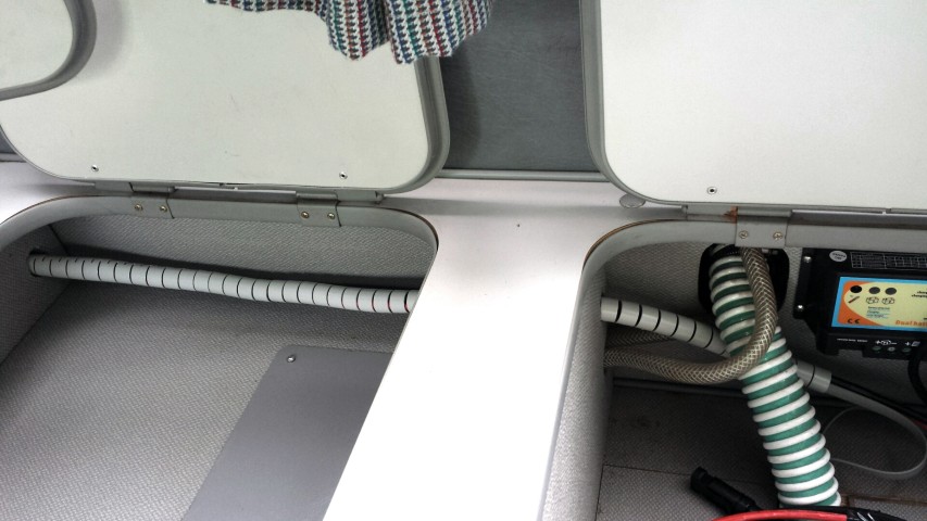
Here you can see the full run through to solar controller.
From wardrobe to cupboard
To neaten things up a little i have wrapped the cables in some cable tidy. I brought this from Maplin (UK) and was pretty pleased with the fact the colour is light grey. Far less obtrusive than black or white (although in the picture below it looks a little more obvious than it does in the flesh). The length was just right and i managed to feed all of the cables into the tidy and push it through the holes so it is one unbroken piece. It feeds all the way into the wardrobe and as far up as the outside of the wardrobe so a real neat job if i don’t say so myself. 🙂
Cables wrapped
Next I ran a two core cable from the controller to to leisure battery at the front. This was simply fed up through a gap in the unit and cable tied to the vent grid behind the cooker / draining board and sink. It then drops down into the cupboard.
Cable feed to leisure battery.
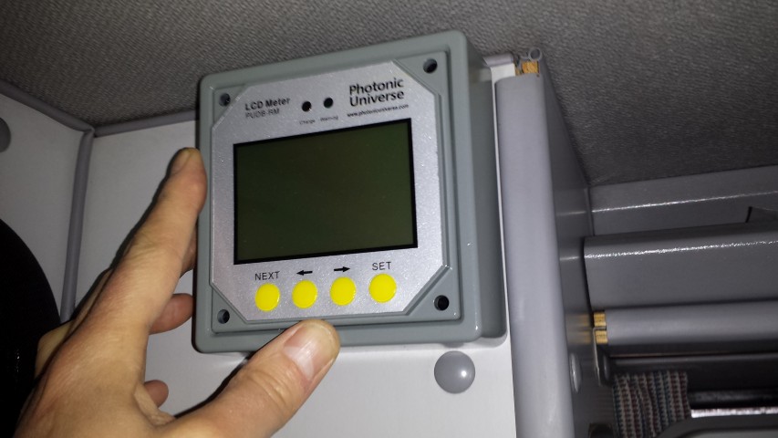
Below you can see the LCD display unit matched up in the location it will eventually sit. Not a perfect colour match but much better than the original black colour.
So the next thing to do was to wire everything together. I noticed that in the installation manual for the solar controller it states.
‘although the solar controller has built-in electronic protection, for safety and added protection please install inline fuses into the circuits between each battery and the controller, on the negative wire, as close to the batteries as possible. Current rating of fuses should be chosen according to the maximum power current / short circuit current of your solar panel’
I was a little confused because the printed installation / information manual that came with the controller also states that there should be a fuse fitted in the live from the solar panels also. So off I went to Maplin to get a couple of in line blade style fuse holders. I established that the rating of fuse i would use for both sides of the feeds would be 15amp. The short of each panel is just shy of 6amps so x 2 = 12 plus a little extra. I’m not an expert but my step dad (ex tv / radio engineer) confirmed this would be the rating i would need.
After a bit of wire stripping, soldering and heat shrink application I was all ready to connect everything. I had not gotten round to running the second battery cable to the diesel starter battery in the engine bay, but the dual battery controller will function quite happily with a single battery and does not have to have the second battery connected. Ultimately I want to get the starter battery connected. The charge from the controller can be split between the two batteries by percentage. I am thinking a 20% charge to the starter and the rest going to the leisure battery (house for those in the US) should work quite well for prolonged periods being static. This should maintain a few amps to keep enough charge in the starter battery to make sure we don’t get stuck, but the majority of the power will be diverted to the living area for TV, radio, phone / tablet charging and interior lights.
So here is the final install with the controller / LCD meter connected.
Controller Wired up
The only setting I had to change on the solar controller was to the battery type which should be set to Type 3 for ‘Flooded’ (Lead acid) battery. The other options are AMG and sealed (I think?).
LCD Display
Here you can see the LCD controller connected. I fixed it to the wardrobe unit using double sided foam pads. Having fed the data cable over the wardrobe top the flat cable was very tight and forced the face front out and away from the units. The low profile of double sided tape would have made everything tight and probably wouldn’t have given the extra couple of mm required to mount. However, the double sided foam allowed that extra distance to mount. It does tend to rock a fraction when the buttons are pressed as the foam gives a little, but this is livable and far better than drilling and self tapping the display into the wardrobe unit. I’ts pretty secure and certainly isn’t going anywhere in a hurry (*See amendment at bottom of page). Also, it’s a novelty now so I am having a play and seeing what does what, but I am sure I will settle on a particular screen that will give me the information I feel most appropriate and leave it set to that….in time 🙂
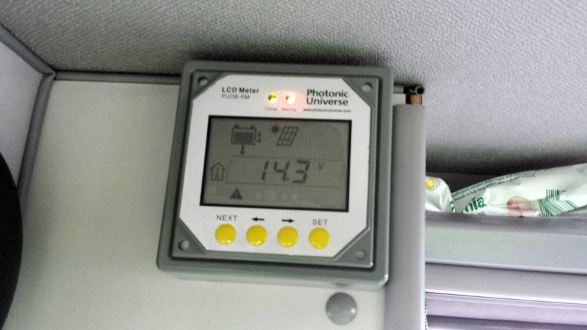
You can see two lights on the display. One is green showing that the panels are charging 🙂 , the second is red showing a warning 🙁 . The annoying thing is that the warning is just to show that the second battery isn’t attached. As said previously the controller functions perfectly well without a second battery, but there is no way of acknowledging you are happy with one battery to remove the warning. Anyways, all in all I have a working system so win, win 🙂
LCD Display Illuminated
UPDATE
It seemed a shame to have all of this available power, yet only a single leisure battery to save it to. So my next job was to source a suitable battery that would fit in the compartment behind the right hand (passenger) seat. This would be linked directly to the first battery giving a larger source of power to draw from. The one I chose was advertised as a T25 battery on ebay and is branded Xplorer. The seller is alpha_man_batteries. This battery combined with my existing would give me a total of 180ah 🙂
I decided I would get this done by an auto electrician as it would involve feeding cables under the van and i preferred it to be done correctly. I did mention to him that if he had time that he try and route a cable from the solar controller to the starter battery in the engine compartment. I had quite recently been made aware that the interior lights run off this battery and i was mindful that this would reduce the chance of finding myself in a position where i could not start my van should too much power be used. It was at this point I also made the decision to change my fluorescent interior light for LED (Guide here LED interior light upgrade)
After two days I collected my van and was really happy with the work he had done fitting the leisure battery. As an added bonus he had managed to route the cable from controller to starter battery. This is the leisure battery. As you can see it’s snug but not not too obvious when the compartment door is closed.
Battery
Door only slightly proud
Door only slightly proud
Here you can see where the black cable for the starter battery enters the wardrobe (right) , and feeds through a hole he drilled in the floor, which in turn is fed into the engine bay and round to the battery. The hole was sikaflexed to stop water ingress.
Routing of cable in wardrobe from solar controller to battery
Below you can see that the LED solar display is now showing two batteries connected and the red error / warning light has gone out 🙂
Well that’s pretty much my solar install from start to finish. I hope this has been useful and if anybody needs any more information please leave a comment and i will message back accordingly 🙂
Andy
*Amendment
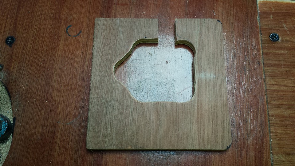
Although the LCD controller appeared to stick to the units like glue with the foam sticky pads, I think the change in temperature on hot days \ cool nights was enough to upset it enough and it kept coming away leaving it hanging from the data cable. I realized that the surface area of the small foam pads on the thin outer edge of the display molding wasn’t enough to keep it in place. This got really frustrating so i set to concocting a more permanent fix. This consisted of a piece of ply board cut to shape and painted grey to match the interior of the van.
Cut Ply Board
Painted Grey
Four holes were drilled in the board to match up with the holes in the LCD display unit. I brought 4 stainless countersunk head screws which were fed in from the bach of the ply board, through the display and tightened up. The strange shape hole cut in the ply allowed the data cable to feed out of the back. The controller has a much greater contact area at the rear of the display for double sided adhesive tape, and as a result has stayed firmly in place since mounted. Result 🙂
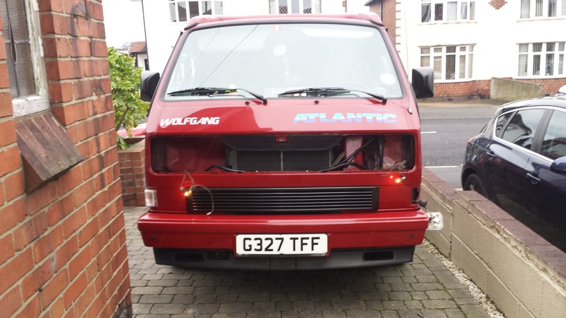
I had frowned at the South African grills because I felt people were paying well over the odds for a grill that was just a ‘bit’ different in the UK. However, the first time I saw Terapodz in the flesh was at the T3 Bus Meet. To me they added extra function and extra character above and beyond a wrap around to the indicators.
So these were on my Xmas shopping list. Fortunately my wife had caught wind of my wanting and bought them as an early Christmas present. Suffice to say, mid December I was adding these bad boys…
Lights out for install
Terrapodz fitted
All back together 🙂
Sorted 🙂
Update (2019). All of the surface mount LEDs have failed on one lamp, and some have failed on the other. This happened over a period of months so really disappointed as they were not cheap. Would I recommend them…No. However, there is a second generation coming out I am told, but I can’t get my money back so it’s going to be a repair job or take them off!
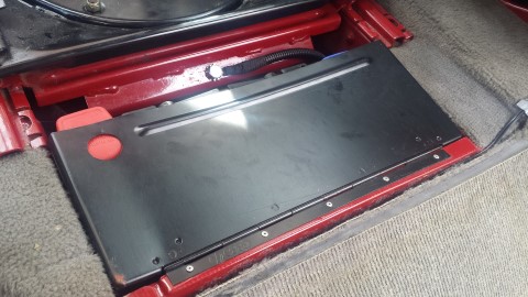
This cover was brought from Brickwerks. I was in two minds whether or not to buy one as it would hide the polished Brickwerks Stainless Exhaust I fitted a few months previously. However, after some deliberation I decided that, as with the Engine Under-Tray tinware, this was a component fitted from factory (if not in stainless).
I have decided that although it looks clean, it also looks white. Sure it’s brushed stainless, but for me I think in the end it will be colour coded cherry red (LA3E) to match my van.











 T
T