the Westfalia conversions are a very well thought out camper, and after owning mine for 5 years I have address many of the things that I have not been happy with. That said the sunroof has been an optional extra that i can see no good use for. In the winter it is the only part of the van that gets condensation to the point it wets the front seats and continually needs to be wiped dry. In the height of summer the sun can become rather irritating whilst driving around midday, which may sound a little ungrateful, but its not a pleasant feeling when its hot. Similarly, in the summer when the sun starts to rise early its surprising how much light enters the van through the sunroof waking us earlier than we would like. So its taken a while to get round to sorting out a solution, but I’ve finally done it.
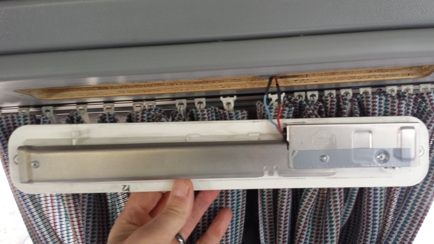
As with any fabrication its always a compromise, and its made more difficult if trying to do it sympathetically. What I mean by this is to try and keep the modifications fully reversible by not drilling holes or screwing into the existing structures in case I want to revert back to OEM. With this modification I chose to take out four of the twenty or so self tapping screws that hold the bottom part of the sunroof frame to the roof, and substitute these for longer ones that would hold the cover in place. The base material for the cover would be 3mm hardwood ply as this was light, thin and strong.
I created a template and carefully cut the wood using coping saw .
The four self tapping screws were dabbed with paint and the board was offered in place whilst the paint was still wet. This provided me with an accurate location of each hole I needed to drill to secure in place. I varnished the board to seal the wood and stop it warping when in place. This would also provide a good base to glue the other materials to.
Above you can see two lengths of aluminum which would support the structure from below when fitted, and four circles for the mood lights. I could have just made a basic cover to block out the daylight, but I thought I would go the extra mile and make it more of a feature by adding the lights.
Here I used tracing paper to create three templates I would be using to cut the grey rubber mat I would be bonding to the surface of the board. This would give it more of a factory finish along with providing a little insulation.
Two of the three grey foam elements in place. Just gluing the aluminum bars
Above you can see two of the three grey foam elements in place, and below the third and final piece being held down by weights as the contact adhesive sets.
Third and final foam element in the center of the board being held down by weights as glue sets
Other than the wiring that needed to be extended towards the rear of the van so that the light switch was next to my other mood lighting switch, the process was just a little fiddly / time consuming rather than complicated. Most of the items inside the cupboards needed to be removed to run the cables to the rear, along with the fridge, but it was worth it in the end.
This was the second attempt at utilising the available space below the compressor fridge. The first attempt was not brilliant and I kind of knew I wouldn’t be totally happy until I had a solution that was on a par with the chopping board. What I mean by that is the chopping board had a lot of time dedicated to it to make sure it worked and could stand the test of time. The first incarnation of the lower fridge draw was really just an alternative place to store stuff like batteries, fuses, headphones etc. Basically it was adequate, but not brilliantly executed. We were also having to make do with a flaky solution for our cutlery, which was a draw in front of the sink which has a large portion deeply recessed to make way for the sink waste pipe. Don’t take this the wrong way, I’m not having ago at VW or the coachbuilders Westfalia. They did the best they could with the components and space they had at the time. But things have moved on and I was going to make sure I took advantage of this.
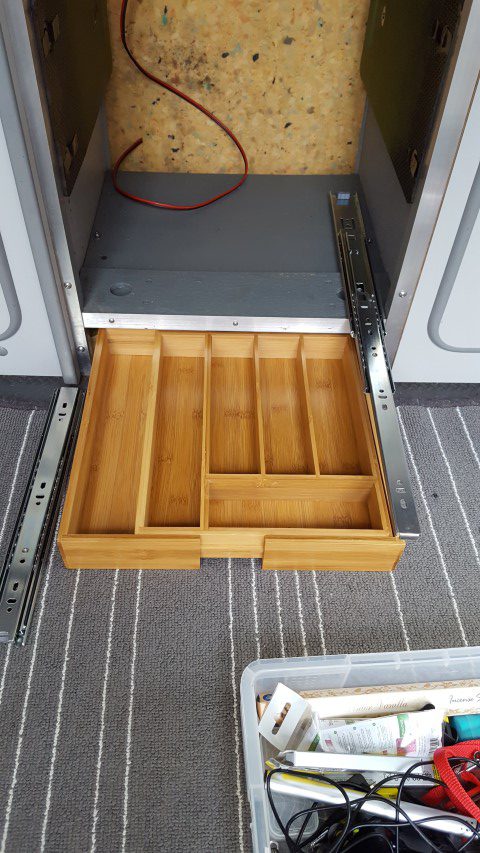
So with all of the above in mind I set to relieving the already crowded cutlery draw by relocating below the fridge. This meant that the fridge had to come out along with its shelve. I worked out the space I had to work with and started to look around for suitable parts. I knew that it would need to slide out a lot further than the chopping board so a pair of double extending draw slides were purchased from Screw Fix (UK). From there we took a trip to B&Q and found an amazing solution which would save a great deal of time in this project. Basically its a bamboo cutlery drawer that expands to fit different size draws in a domestic kitchen. This worked really well as all I needed to do was mount the inner part of the hinge into each side of the cutlery drawer, and the outer part of the hinge on the inside of the unit. Simples!
Components purchased…just a lot more faffing to do 🙂 Drawer fixed to hinge, and hinge fixed to unit
What I did do to make sure the drawer wasn’t going to slide open as I drove around was to mount a block of wood at the back of the drawer to act as a stop buffer. On both the buffer and the tray I attached a magnet so that it would connect as they became close. As you can see from the below video, everything seems to be working a treat 🙂
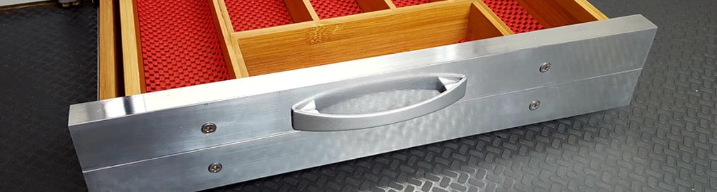
So this was all well and good, but I needed a front facia and handle. Fortunately the DIY suppliers provided aluminium angle extrusions that perfectly matched half of the depth of the drawer (See below as I measured for size).
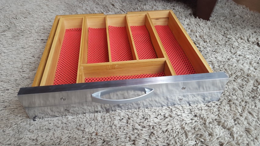
So I cut two pieces to the required width, drilled, countersunk and screwed one at the top, and the other at the bottom.
Handle fitted to match the Chopping board. Red anti rattle foam dropped into the compartments.In place Nicely flush with the bespoke surround
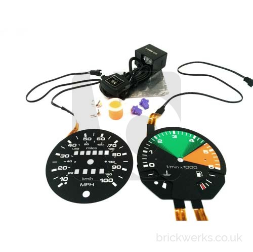
My stock speedometer is woefully inaccurate. It used to read in kilometres per hour due to its European origin. To try and make it usable in some way shape or form, I fitted a Backlit Gauge Kit from Brickwerks.
The kit certainly adds that modern look to the dash and converted to MPH. However, I think in stripping the speedometer to installing the kit I may have upset the calibration of the device. That or it was inaccurate before I started tinkering.
Anyhow, knowing that it’s out by a good 10mph, and I run the risk of getting a speeding ticket I tend to use an app on my phone to accurately monitor my speed. This is all well and good, but a tad inconvenient.
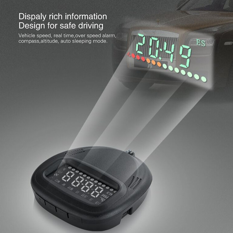
With all of this taken into account I have decided to look at a Head Up Display (HUD) GPS speedometer. It’s cost me £38 from eBay.
I’m going to have it wired into the ignition live so it comes on automatically and test it on my dash pod. The other option is to plug it into the cigarette lighter (12v) socket but this is too messy a solution for something I want to work each and every time I use my van.
It’s yet to be delivered, but I’ll post up with feedback once installed ??
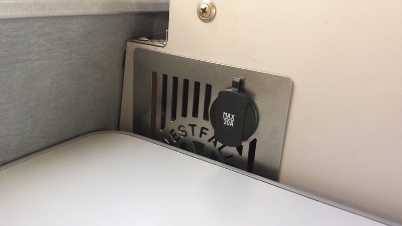
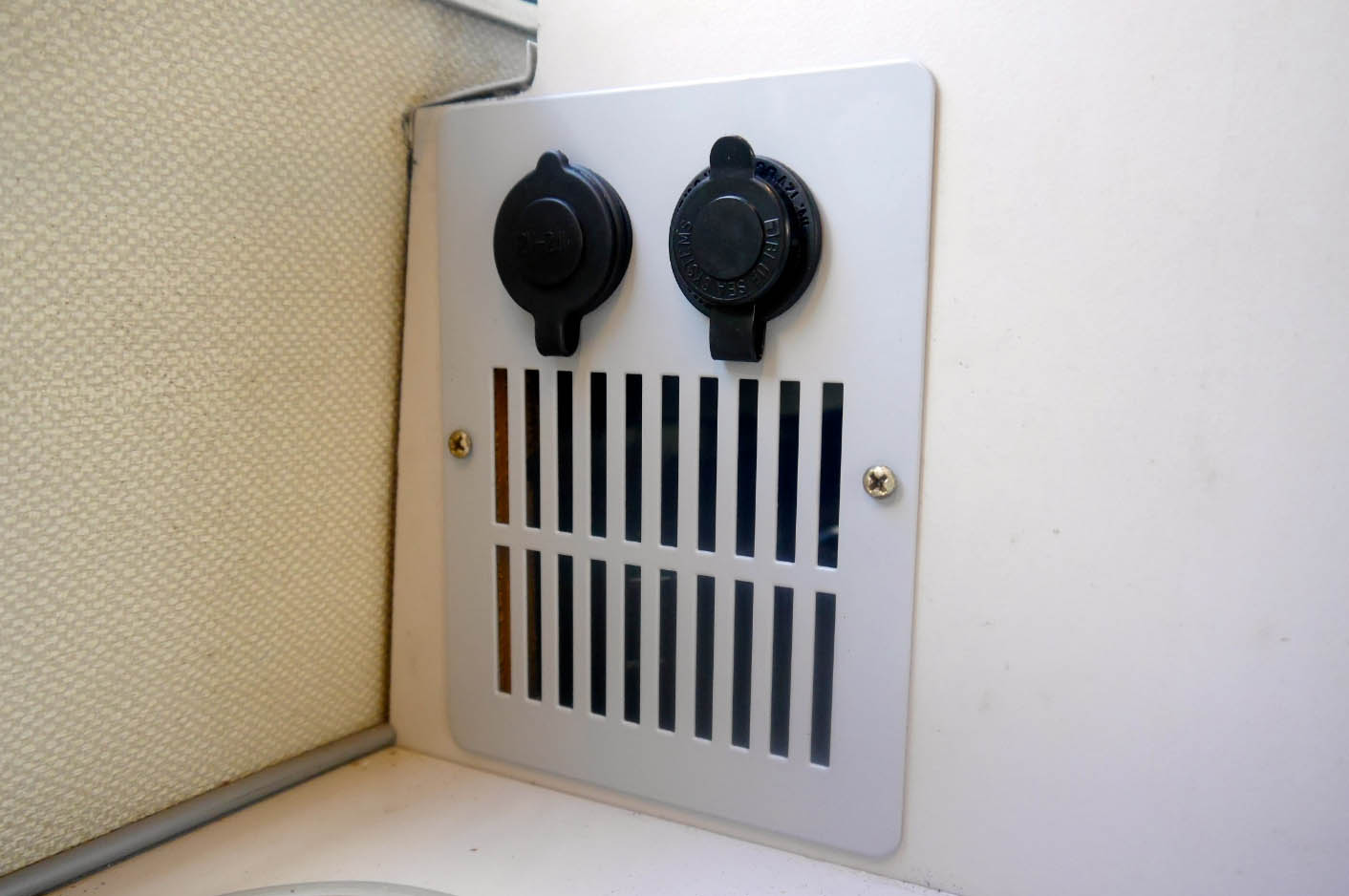
Some time back I had replaced the original rusting fridge vent for a stainless one with a 12volt socket incorporated. This was obviously an upgrade, but since I had installed my solar panels we have not had to use electric hook up and this will be the case for the foreseeable future. The knock on effect of this is that we don’t have a 240volt option for charging phones tablets etc. So the single socket we were relying on in the stainless vent just wasn’t enough. It looked nice, but function was more important now.
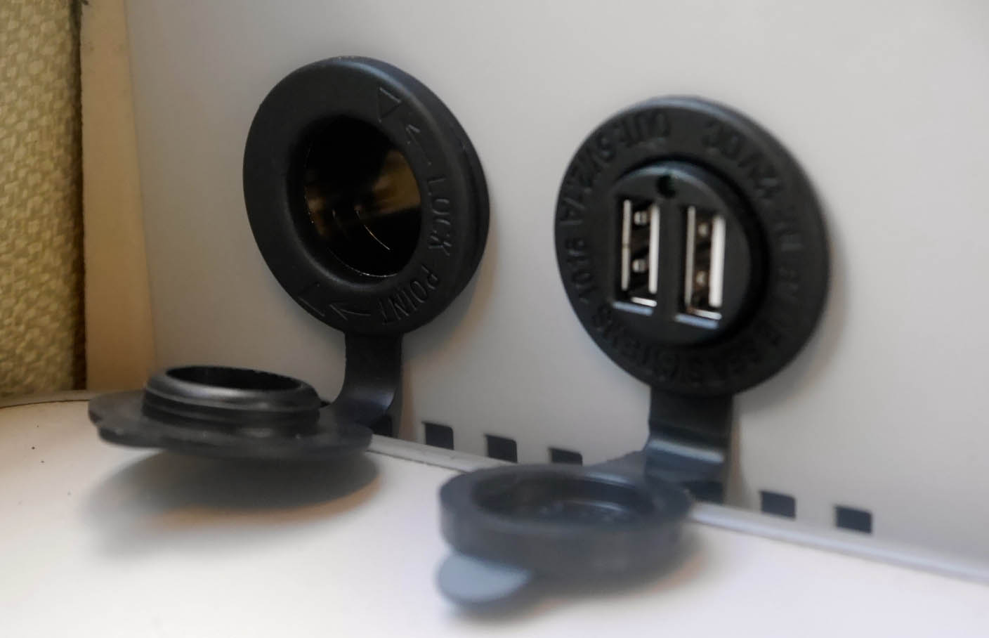
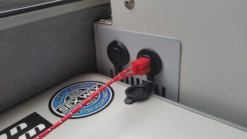
Seeing the Campervan Culture ‘multi socket fridge vent it looked like it would answer all of my prayers. The grey is a good match for the later Westy interior in the Atlantic, and installation was pretty straight forward, daisy chaining one socket on to the next with the main feed from the leisure battery (fused at 20A) .
CVC 12v Fridge Vent Socket
So here is my installed unit with a splash of red from my braided USB cables courtesy of the Pound shop (they were £1 before you ask 😉 ). We have only done a couple of weekend getaways since installation, but it’s already come in really handy!
Knowing I had the extra space below the new Waeco Fridge , and not wanting it to just get used as a lazy storage area where things would get crammed and look messy, I decided to make a drawer. This was always my intention, but rather than be prescriptive and methodical from the outset, this had to be fluid in its design. Basically the slide out chopping board established the height the fridge needed to sit in the aperture available. It wasn’t until I had fitted the fridge that i knew the depth i had to play with for the drawer. The ‘hole’ has been handy to store some tools for the last month or so, but items like these that should only get used occasionally, are far more suited to a less accessible area, freeing up this space for things that get used in a daily basis.
So the draw….Initially I was thinking of a drawer on rails. In fact i brought two pairs of rails, one for the chopping board which are utilized and effective at present, and the second set for the drawer. However, the slide out action of those particular rails is such that they only extend about 30cm out. For a drawer that has a depth that goes back far further than that it didn’t seem like an effective use of space if you can only access the front portion of the draw. There are other rail systems that extend out double the length of the rail, but these tend to be quite deep in design and would take up quite a lot of the already limited space, making the draw a lot narrower.
So the solution was a far simpler one than having to mess around with rails. We found a very low profile storage box that had an insert for the top portion allowing small items to be segregated. Things like fuses, light bulbs, remotes for devices etc. The bottom part was shallow, granted, but this would be for our tablets, blue tooth speakers etc. We brought the box from Rymans, and if I am honest it was a bit of a stab in the dark in terms of the size . I’ve got a pretty good eye for judging space and to me it looked too deep, which actually turned out to be the case. However, when the lid was taken off it fitted perfectly. So we lost the lid, which probably would have become a bit of a hindrance anyway.
So the basic elements can be seen here.
The basic elements
It doesn’t get much more complicated than this and it took me best part of an hour to construct. The drawer handle had been brought at the same time as the handle for the slide out chopping board. The white thing in the photo above is the aluminum sheet with its protective film on (which was a slice of a larger sheet that a friend got me for another project). All that was required to complete the construction was a small spacer to bridge the gap between the internal tray plastics, and the extruded strengthening elements surrounding it. This came in the form of a piece of hardwood that I found in my wood-store. Two holes were drilled in the Aluminum, wood and plastic tray to marry up with the holes on the handle. The screws for the handle needed cutting down a fraction, but all in all it was a really simple process.
Draw complete with top divider
This was all knocked together without having access to my van as it was in storage so I wasn’t 100% sure it was going to fit. I had used the original Westy fridge as a reference as this was in my garage, and a few photos of my fridge install from my phone. However, I was relieved to find that the drawer fit perfectly 🙂
At present the drawer is no more than a push under tray with a suitably matching front fascia on. I will most likely stay in place during transit, but I have acquired some very small, high power magnets. I plan to stick a couple of these on the back top edge of the aluminum drawer fascia, and a small countersunk head, ferrous metal screw at the corresponding edge of the framework on the lower fridge support. This should allow the drawer to locate shut with a nice crisp click 🙂
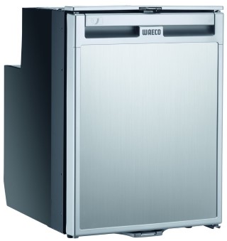
My main reason for upgrading my fridge was due to the fact I had established a very effective Solar Install. It seemed silly not to take advantage of all of that free energy to power a compressor fridge. This type of technology is far more effective than the stock fridge at doing it’s job. It actually has a dedicated freezer draw which is great for Ice Lollys on a hot day 😉 .
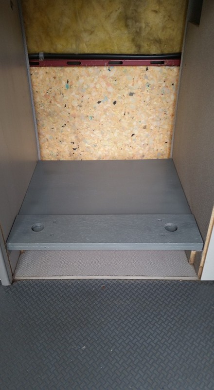
Anyways, on to the installation: I wanted this to sit just below the slide out chopping board as I wanted to maximize the depth of the draw I am going to fit below it. So after some careful measurements i set to positioning a couple of pieces of angle aluminum to sit the shelf on. The shelf was then made by two pieces of marine ply. The first was the full width and depth required to seat the fridge on. The second was a slimmer piece with two holes drilled into them where the two front feet of the fridge will locate. This will stop the fridge from sliding about as there are no real fixings as such everything is having to be bespokely made. The two pieces were glued and screwed together and painted grey.
After this i needed to find something that would provide padding either side of the fridge to wedge it in place. I wanted this to be something that wasn’t going to get affected by damp or humidity, but provide a nice gentle compression on either side of the fridge. After some time i decided that kneeling pads would be just the right depth to bridge the gap (the sort of thing you get for gardening). These cost me £1 each from Wilko . These were sprayed black at the front and they were screwed to the inside of the fridge compartment (two screws at the front and 1 at the back. each screw head had a large washer on it to pull the padding in and I tightened the screws up enough so that they sunk in and didn’t catch the fridge when being slotted in. The heads were also covered with a piece of insulation tape to be ion the safe side.
Here you can see the fridge in place:
From here on it was just about trimming the surrounding area. I brought angle aluminum from B & Q and cut and drilled to size. I had to make some bespoke brackets to mount the whole lotso it wasn’t straight forward. However, i’m pretty happy with the end result
This has then been connected directly to the leisure battery with a 5 amp fuse in line. I really need to get an additional fuse board fitted as there are way too many connectors tacked on to the battery at the moment. I will seek to have this done professionally to get things tidied up PS. There is a gap either side of the fridge of about 5mm. The finished photo here doesn’t show that and is a little miss leading. I feel this is enough of a gap to let air circulate and stop any rattles through vibrations.
My decision to change the stock 3 way fridge for a 2 way electric model meant that I would have a lot more space to take advantage of in the same space. I saw a post on social media where somebody had put in a pull out chopping board, and although it was not executed very well the idea stayed with me.
So I set to looking for the components to full fill my ambition. My wife and I went to IKEA one weekend and I saw a chopping board that was made of bamboo. I knew it would be too big for the aperture it needed to fit, but I was fully aware that I would be very lucky to find something that would fit perfectly without modification. A few days later we went to the local B & Q store to get the rest of the components.
Basic elements
Over the course of about four days I sawed drilled and screwed these items into something that looked like it would work.
Pregress
And this is the end result.
I think this will prove very useful. In a van that has very limited space, it’s things like this that will make all of the difference. Just need to get the fridge installed now. Watch this space 😉
Westy Specific (but may help owners of other conversions)
My reason for replacing the original fluorescent tubes for LED was purely down to the fact i had completed my solar install and wanted to increase my efficiency and reduce my ties to electric hookup. I had previously brought a 300mm LED light to test the water last year. This was unbranded and didn’t claim to be warm lighting. I didn’t mind at the time because the way I saw it i could use the one light when off grid to reduce the power we were using. However the tube was very bright to the point where we didn’t really want to use it unless we had to. Since i brought my van, and time has gone on, i can certainly see the benefit to the ‘warm glow’ LED lights.
All of that said, the one LED i had installed above my sliding door was still fitted with the ballast controller designed to start the old fluorescent tube. This decreased the efficiency & brightness of the LED light. So after receiving my new tubes from Campervan Culture, i saw the advisory note on the packaging to bypass the ballast. So I started to strip down the light unit and tried figure out what this meant. After a dismally failed attempt at getting the wiring right i decided to create a user guide for the Westy owner that may want to complete this modification. This may be helpful to owners of other conversions, but i can’t say for sure. I would imagine the basics are the same.
The first thing to do was to isolate the power supply by detaching your battery. As standard these lights run off the starter battery so that’s the one you need to detach. (Note: Modifications can be made to run these lights off the leisure battery so bear this in mind if you find your lights are still working after detaching the engine starter battery). After this you can go ahead and remove the light unit from the ducting.
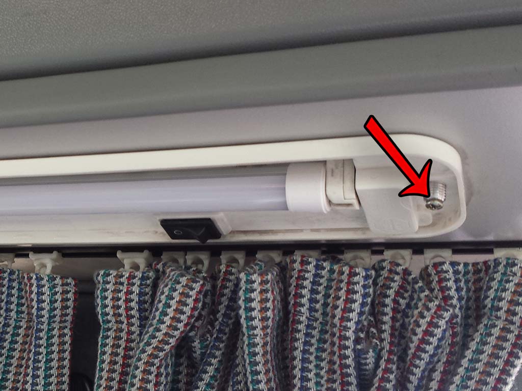
There are three lights in total. One is above the sliding door and the other two are on the opposite side above the cooker and rear table. All are unscrewed in the same way. Firstly the two black knurled plastic lugs are removed with a flat bladed screwdriver. This allows the clear lens to drop out. This also gives access to a cross head self tapping screw pictured below. Remove these whilst supporting the light.
The light on the right hand side above the sliding door can be disconnected by detaching a couple of spade connectors. Unfortunately the two on the left of the van reveal no such connectors. So for these two the cables must be cut to remove.
So this is the back of the light on the work bench. It soon becomes apparent that there is no way of progressing this without removing the pop rivets that hold the unit together. I did this using a pillar drill. However, a suitable workbench and careful use of a drill should suffice.
You can get away with drilling out only the three rivets pictured above. The two outer rivets will enable you to remove the ballast enclosure from the lamp, and the center pot rivet secures a transistor to the aluminum housing. Use a drill bit to take off the head off each rivet being careful not to drill too deep. Once this is done the whole of the ballast unit should be able to be removed far enough away to use a bradle or small gauge screw driver to push out the rivet body and release the aluminum from the ballast electronics.
Next detach all of the wires that connect the PCB ballast to the wires using a soldering iron! So this is what we have removed …..
Ballast Electronics
I will say at this point that i did actually drill out the last remaining rivet holding on the long aluminum strip covering the long wires, so the images below reflect this and may not represent what you see. It allows you to see the wiring a little more clearly in this guide. I would recommend leaving it in place.
Image 1
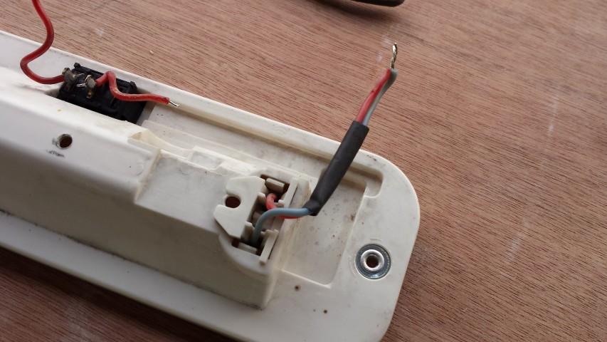
The rest of the guide is just a case of taking what we are left with and putting it all back together in a way that works with the new tube. Ignore the color coding of the wiring from now on. Basically we need to provide a positive and negative connection to each side of the new tube / bulb. Using the wires we have de-soldered from the ballast, strip back the insulation on the two longest wires by approximately 1cm so there is enough wire visible so you can twist them together. Solder them together and then solder the spare light blue wire onto them in turn. Cover the join with heat shrink. This can be seen in the picture above (the long cable in the lower half of Image 1.)
Image 2
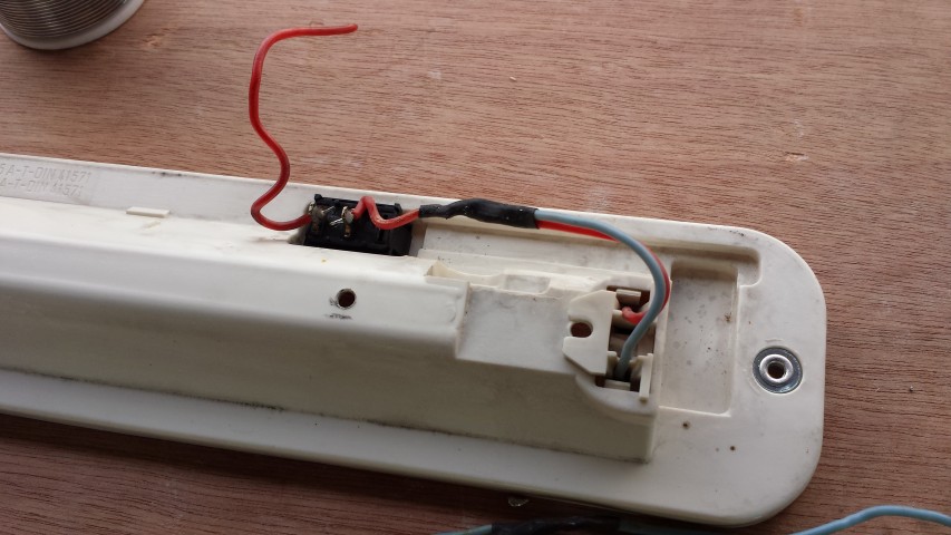
Next do the same to the opposite end. Strip the wires back, twist together and solder (Image 2). After this connect these two wires to the on / off switch and heat shrink to insulate the connection (Image 3).
Image 3
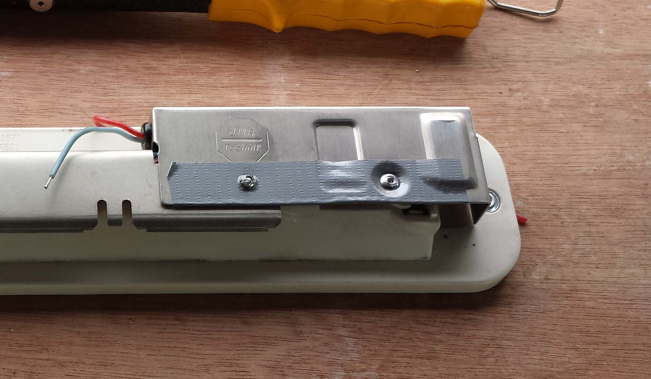
The jury is out as to which way you go with this next part. I don’t actually think this is really necessary to re-attach the aluminum box that contained the ballast electronics as there is really nothing left to protect. However, i decided it was going back on if for no other reason than to keep the cables from getting trapped between the lamp and the ducting whilst fixing to the van. Taping in place would achieve the same objective i guess but for the sake of a couple of rivets I chose to fit the casing. I covered the inside of the aluminum with insulation tape just to be on the safe side to stop the wiring on the switch from shorting out on the metalwork (belt and braces). I used a braddle to create the two holes in the insulation for the pop rivets.
Insulation
Next i found appropriate sized pop rivets from my multi pack collection brought from ALDI . I will try and establish which sizes i used where, and feed back. So the below image shows the cover connected after feeding the positive and negative feeds through the small hole with the grommet.
Close up
So the unit it basically built up and should work with your new LED tube. Just re-connect to the wires in your van using solder and heat shrink…If the bulb does not work turn it over and re-insert. LED’s will only work in one direction.
and screw back in place
The lights should use less power than before and be slightly brighter as a result of loosing the ballast. 😉 .
I saw these kits a few months back and thought they looked pretty cool. These backlit gauge kits are fitted over the original gauges to bring the clock bang up to date. The purchase of a Porche steering wheel made me think that this could be the kit i needed to go the whole hog and change the driving feel of the van. Still not 100% sure about the steering wheel as I haven’t gotten round to fitting it yet, but I’m pretty chuffed with the gauge kit (photos to come)
My wife Mandy had seen the front tables fitted in other vans and thought it would be a good addition to ours. I wasn’t convinced initially, but the more we camped the more it seemed like a good idea. We were continually using the rotated front passenger seat to position the TV when in day mode, and then we would drop the cooker cover down and re position it there to elevate so we could watch TV in bed. We also struggled to find a place for pots we had used, but the addition of the front table over the drivers seat has been a massive bonus for both TV and any pots. This has freed up the passenger seat if we want a change of viewpoint in the van.
So we bought both the leg and the leg mount from NLAVW website. They seemed to be the best prices. However, both parts were the earlier type Westfalia items. This wasn’t a massive issue to be honest and I decided live with it. The items were galvanized and weren’t that pretty so I choose to color code grey. I already has a tin of etch primer and brought a can of spray paint from Halford. I scoured the car paints and couldn’t find anything that fitted the bill. I found a colour that looked like it could work in a miscellaneous section more for household work. It was called ‘Industrial Grey’ . So i got home and gave it a coat. I couldn’t believe how good a match the paint was against the carpet.
Colour coded and ready to fit
I did the same with the leg. When it came to fitting the bracket i decide to take the leisure battery out. I chose to drill a small pilot hole in the body to provide a good biting point for the self tappers. I didn’t want to damage the battery while doing this so i played it safe. Anyways, all went smoothly and within an our it was all fitted and ready to go. 🙂








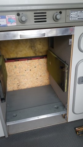
 . These were sprayed black at the front and they were screwed to the inside of the fridge compartment (two screws at the front and 1 at the back. each screw head had a large washer on it to pull the padding in and I tightened the screws up enough so that they sunk in and didn’t catch the fridge when being slotted in. The heads were also covered with a piece of insulation tape to be ion the safe side.