A little progress on the gearbox…Due to issues with a batch of faulty parts, the gearbox wasn’t ready for my September holiday. As has been covered in a previous post we managed to get away thanks to a friend lending me a box. Ironically, I received an email stating my gearbox was ready the first day of our three week break. Suffice to say I was not really in any positing to collect until the end of September where it sat in my garage until a couple of days ago.
The box build spec changed from standard to include a 4.14 final drive, stronger 4 pinion differential and new differential bearings. This should compliment my new, more powerful AAZ engine with longer gears throughout and a higher cruising top speed.
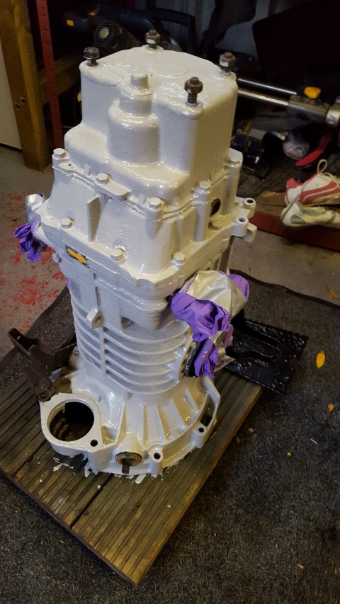
Knowing that the gear boxes are prone to corrosion due to its position underneath the camper in front of the engine, my intention was to paint the casings before fitting the box. I thought about etch primer (the yellow stuff that comes out of an aerosol can), but decided to try Hammerite primer on a small section of the alloy to see how well it adhered. After a couple of days I checked and it seemed to have keyed on really well, so the rest of the box was painted.
I am in no great rush to have the box fitted, and the reality is it’s probably going to sit in my garage for the next 6 month until my van is booked in for a service at Brickwerks. I’ll get them to fit it then 🙂 . Hammerite takes a good few weeks to cure, after which I will paint again with a mid grey engine enamel.
After the epic failure, and massive disappointment of not being able to have our dream holiday in the campervan back in May due to mechanical issues, the agony has been prolonged by restrictions on using the van over any distance until the gearbox has been replaced. A lengthy lead time of two months on getting my gearbox into the specialist left me feeling slightly frustrated, but mid July arrived and the box was delivered in person.
A month or so later and the refurbishment of my original gearbox seemed to be taking a lot longer than expected. Not exactly sure why but I’ve decided to take a friend up on the offer of loan gearbox to tide me over. I originally considered this option a couple of months previously to keep my van mobile in the interim but decided to wait. However, as my September holiday looms I have had to fall back on this as my only real possibility of getting my van roadworthy in time.
Pulling a gearbox out and replacing with another would normally be something I would leave to the experts, but the tight schedule means no availability in the only garage I really trust to do the job properly. So needs must. I rolled my sleeves up and got stuck in. All be it a little reluctantly.
Leaking Gearbox Out
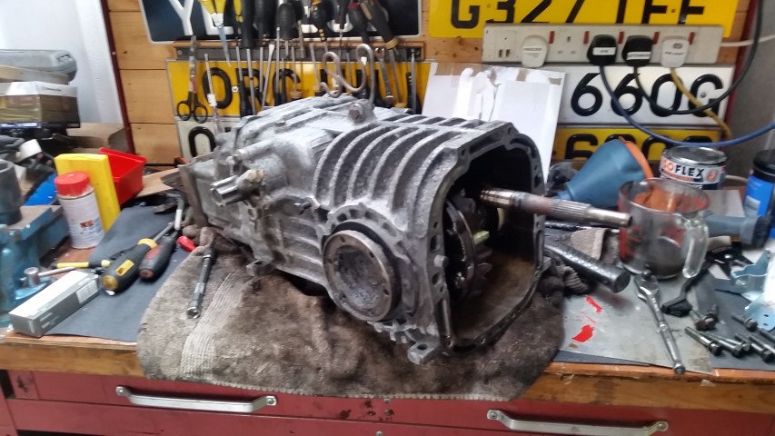
The loan gearbox was petrol, so there was always going to have to be changes made before fitting to my diesel van. The bell / clutch housing needed to be swapped over along with the input shaft. After draining the oil from both boxes I split the clutch housing from the gearbox.
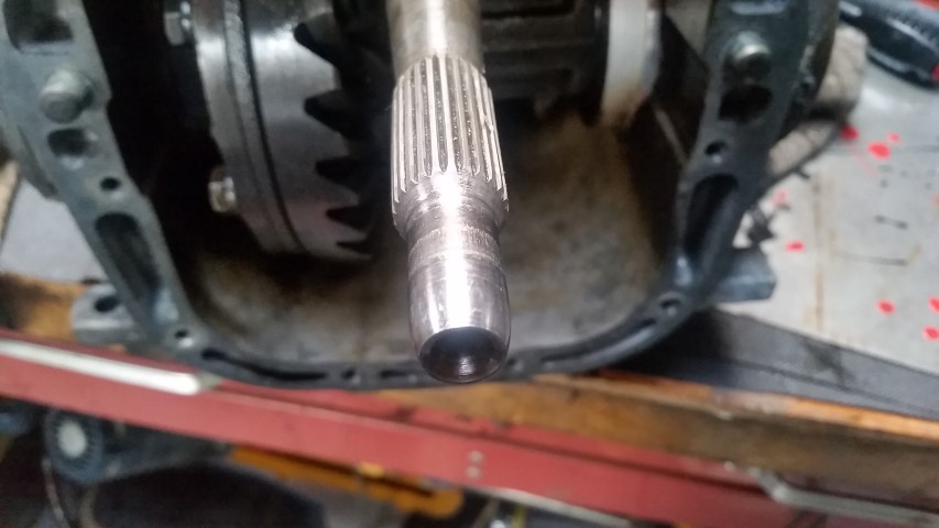
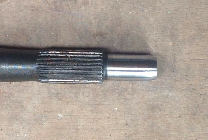
Then I proceeded to change the shaft. However, on close inspection I found the diesel input shaft to be pretty badly worn where it sits in the clutch spigott bearing.
Clearly I wouldn’t want to jeopardize the next holiday by turning a blind eye to something I could rectify prior to fitting the gearbox. So I posted on social media to see if anybody had a replacement I could use. Within an hour or so I had a bite, and by the end of the day I had images as proof of the condition of a good replacement part.
The wonders of Paypal meant that my part was on its way the following day. The clutch housing has also fitted with a new input shaft seal, and 4.5l of gearbox oil purchased in readiness of gearbox rebuild completion. Hopefully, the van should be back on the road in a matter of days 🙂
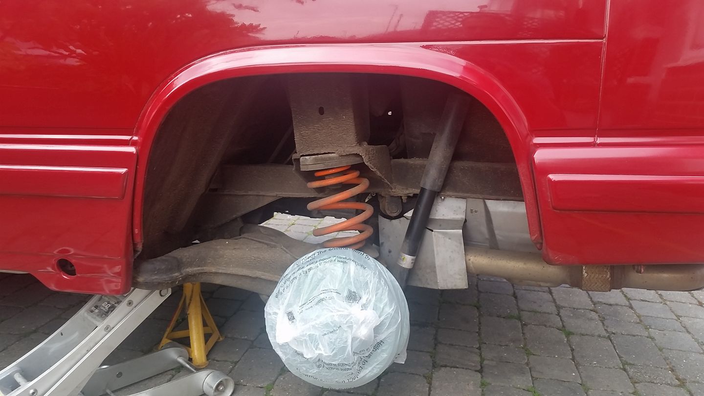
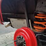
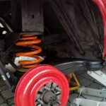
So my van has gearbox issues! But no reason to stop chipping away at the things that have annoyed me until that can be fixed. Basically, the gaps in my wheels aren’t massive because of the style of alloy, but annoying all the same to see the rusty drum behind. So yesterday / today I jacked the van up, popped the wheel off and set to realizing my goal. To paint the drum red.
Anyways, one thing leads to another, and before you know it (5 hours later actually), I’ve washed away all the mud, painted the trailing arms and stone chipped the wheel arch.
The finished article:
The replacement gearbox should arrive on Tuesday, along with new clutch and slave cylinder from Brickwerks (due to be fitted on Friday locally). Nothing like cutting it fine. We should be on the ferry for our Euro trip just over a week later. Lets hope there are no issues with the replacement box!?
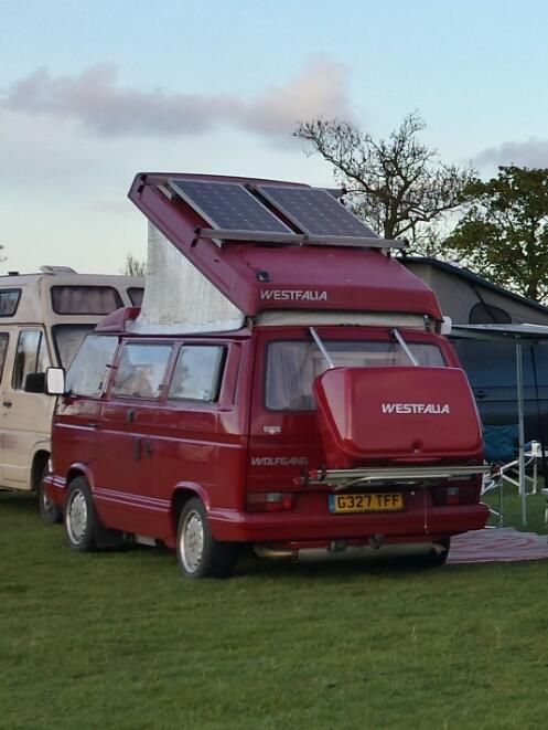
Wolfgang was purchased back in October 2014. Since that time we have used the van for all of our main holidays, and hope that this will be the case for many years to come. All part and parcel of owning a 25 year old classic is the never ending list of things to do to keep it in working order. I have chipped away at cosmetics, creature comforts and the run of the mill stuff to keep him roadworthy. Although changes have been made to drastically improve the handling with suspension improvements and maintenance, there has always been an issue with it’s lack of ability to climb hills.
During a service in 2016 by Brickwerks I asked if they could check the engines compression. Unsurprisingly it has been diagnosed as being on the poor side of what should be expected. This twinned with the fact the fuel pump had proven difficulty to adjust left me feeling that there was only one possible route to give me the reliability I need for any confidence in future trips. An engine change.
last year we made the decision that 2017 would be the year we would commit to a month long trip in Europe. Both Mandy and I explored the avenue of taking time off unpaid to realize our dream so we didn’t have to exhaust all of our annual leave in one fell swoop. This was swiftly agreed by both our employees. Happy days 🙂 .
Shortly afterwards I started asking questions on forums and social media about the best route to go down with my van and its engine. I will not lie, the van had already cost me more than anticipated from time of purchase, largely due to being neglected by the previous owners. So the cost of an engine change was something I hadn’t factored in at this stage in my ownership, which meant I had to be realistic with the budget i felt i could manage.
There are a multitude of different engines that would fit my van, with many of the more modern alternatives providing much better performance and economy. As tempting as it was, I knew that choosing one of these engines would make for a more involved installation, and as a result more costly. Also, a more powerful conversion would require changes to the gearbox to enable it to cope with the extra power, and this was really not an option I could entertain with my budget.
All of this taken into account, I decided to plumb for the slightly larger capacity 1.9td (AAZ) engine as a replacement for my current 1.6td (JX). The extra capacity should give a little more grunt up hills, which will be much appreciated. The almost identical engine configuration would mean that many of the parts involved to fit into my van will already be available from my old engine. That said, getting a good second hand AAZ with low mileage would prove difficult as these engines were produced in the 90s. Many would have high, or questionable mileage and history. Not really a chance I wanted to take from a reliability stand point.
After much pondering and research I chose the only option I felt comfortable with, which was going to be a re-manufactured unit. This is different to a recon engine where the parts a just inspected and replaced if necessary. Re-manufactured is a total strip down and ground up rebuild with all new parts. So with all of this as my criteria for the future power plant, I contacted a company that had an extensive history with re-manufacturing VW diesel engines (AW Engineering Darwen). I was told that an AAZ would cost £2100. However if I had a unit to exchange it would only be £1500. I’m all for saving money if there is a route to doing that, and the £600 discount on an engine with an exchange sounded very apealing. I wasn’t in a position to part with my current engine as we had plans to use it right up until i had the conversion, so the only possible option would be to source another unit.
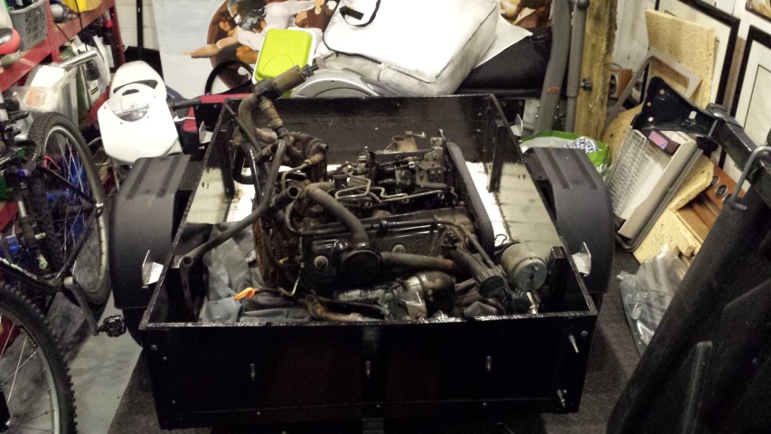
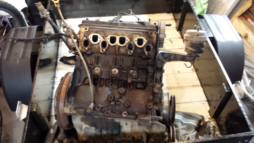
So i spent a couple of weeks on ebay , pre loved and gum tree in search of something that looked like it would tick the box. I eventually found an ABL in Birmingham from a VW T4 Van for the sum of £180 which was promptly collected.
ABL Engine in trailer shortly after collectingABL Engine in trailer shortly after collecting
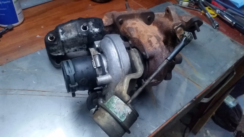
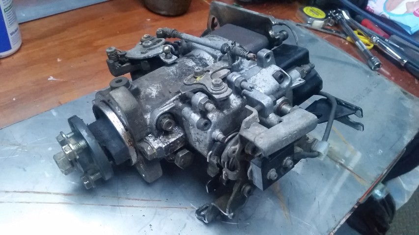
Not knowing the history of the engine I wasn’t sure if it would be an acceptable exchange unit. Basically it had to be salvageable by the engineering company. It was a gamble, but It did come complete with Turbo and fuel pump so I could always sell these on to recoup some of the cash .
ABL Turbo and inlet manifoldABL Fuel Pump
I spent the next day or so removing everything to get the engine in a state where i could make an assessment. It wasn’t looking good…
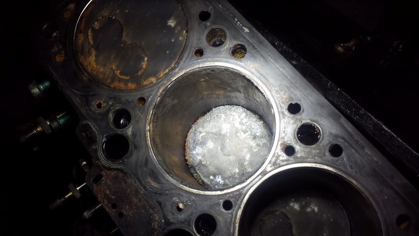
Looking bad for the ABLBuggered Bore and Piston
Big scores in the bore and a pretty badly melted piston pointed towards an injector fault on one cylinder. I sent AW an email with the above photos and they said it would still be worth sending it to see if they could do something with it. I was a little apprehensive as I thought the bore was too damaged, but took the plunge on getting a courier to collect and deliver the engine for £40. So this was £180 engine + £40 delivery = £220 of my hard earned cash. Fortunately it proved not to be a waste of time. I received an email from AW to say that they had managed to turn the engine around, which meant and I would get my discount off a replacement engine 🙂 .
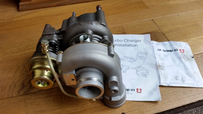
So all of this was July 2016! I wasn’t really in a position to buy the engine back then, let alone have it installed. I knew that this would all take place in 2017 before our Euro trip. So I got an agreement with the engine re-manufacturers that it would be some time in the future before i would be buying the engine. That didn’t stop me looking for other parts. I saw a turbo, brand new on Facebook for £200 which was less than half price so snapped that up.
New Turbo
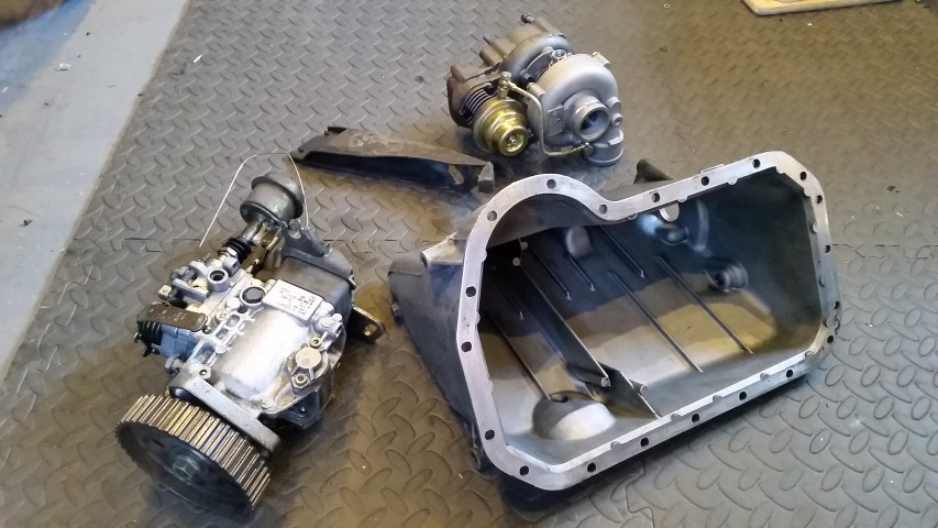
Also, I managed to get a second hand sump that I would clean and use as a replacement for the dirty one on the van, and a fuel pump i would have reconditioned.
Sump, Fuel Pump, Turbo and Turbo Bracket
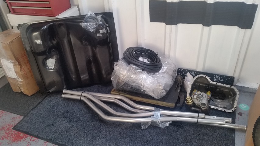
So this is pretty much where things stayed until February 2017. We hadn’t spent any time planning the Euro trip because the finances for the engine transplant and all that went with it started to unsettle me. A decision had to be made, and after a little financial juggling we were back on track. Brickwerks were going to be my chosen engine installer, and a date of April 10th was arranged for the drop off. I knew they had the credentials to do an excellent job as they had done all of the work previously on my van. I also got in touch with AW and ordered my engine which arrived about a week later. I had a few other parts that i should have had fitted by a my local garage last year, but for one reason and another this didn’t happen. So my intention was to have everything sorted in one go. So the parts had started to pile up..
Fuel Tank, Engine, Sump, PAS pipes, Coolant Pipes, Turbo
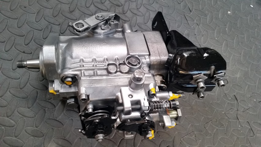
The fuel pump was sent away to Diesel Bob for a check and possible recon. This turned out to be quite expensive at just shy of £400 including postage and VAT. You can see by this picture, its just like new and a work of art so maybe it’s justified? 😉
JX Fuel Pump
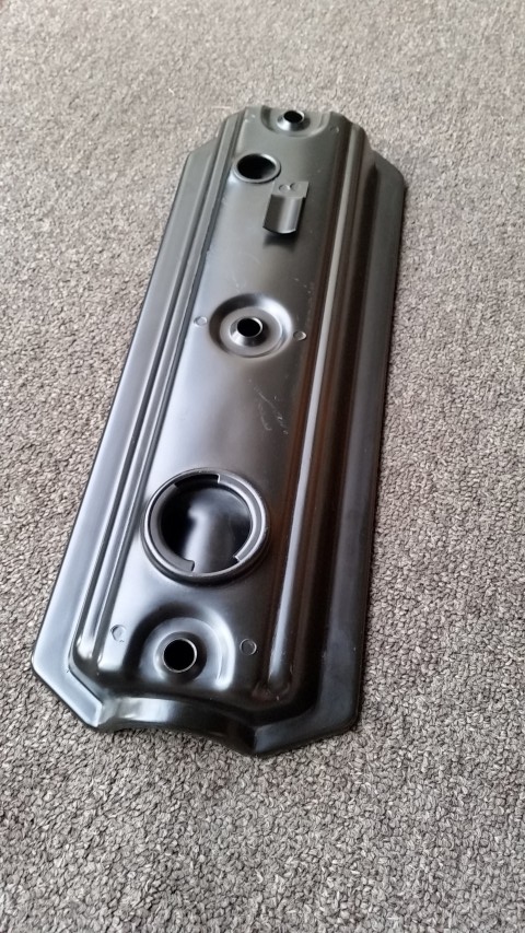
I also managed to source a brand new AAZ rocker cover…result!
So the install date for the engine is approaching, and we are well on the way to planning our Euro Trip with places like Troyes, Anncey & Dijon (France), Lauterbrunnen (Switzerland), and Venice, Garda & Verona (Italy).
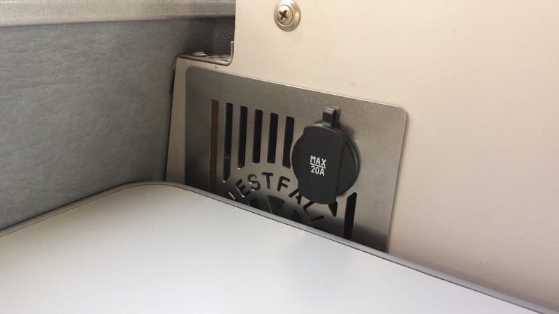
Some time back I had replaced the original rusting fridge vent for a stainless one with a 12volt socket incorporated. This was obviously an upgrade, but since I had installed my solar panels we have not had to use electric hook up and this will be the case for the foreseeable future. The knock on effect of this is that we don’t have a 240volt option for charging phones tablets etc. So the single socket we were relying on in the stainless vent just wasn’t enough. It looked nice, but function was more important now.
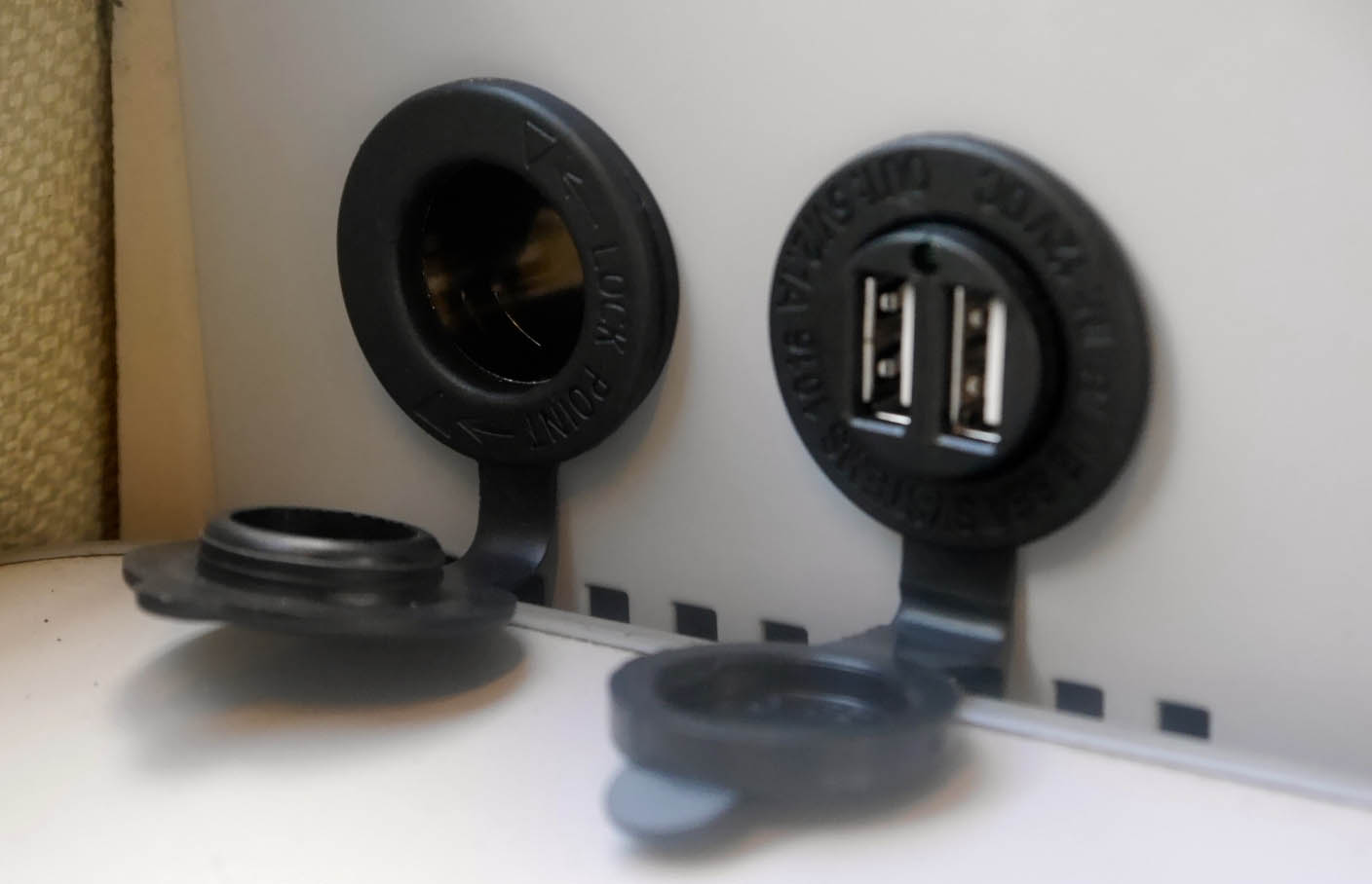
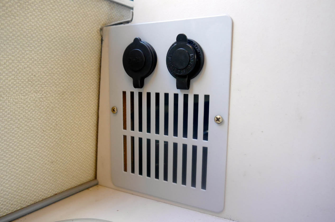
Seeing the Campervan Culture ‘multi socket fridge vent it looked like it would answer all of my prayers. The grey is a good match for the later Westy interior in the Atlantic, and installation was pretty straight forward, daisy chaining one socket on to the next with the main feed from the leisure battery (fused at 20A) .
CVC 12v Fridge Vent Socket
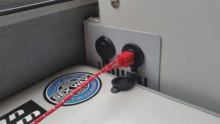
So here is my installed unit with a splash of red from my braided USB cables courtesy of the Pound shop (they were £1 before you ask 😉 ). We have only done a couple of weekend getaways since installation, but it’s already come in really handy!
Knowing I had the extra space below the new Waeco Fridge , and not wanting it to just get used as a lazy storage area where things would get crammed and look messy, I decided to make a drawer. This was always my intention, but rather than be prescriptive and methodical from the outset, this had to be fluid in its design. Basically the slide out chopping board established the height the fridge needed to sit in the aperture available. It wasn’t until I had fitted the fridge that i knew the depth i had to play with for the drawer. The ‘hole’ has been handy to store some tools for the last month or so, but items like these that should only get used occasionally, are far more suited to a less accessible area, freeing up this space for things that get used in a daily basis.
So the draw….Initially I was thinking of a drawer on rails. In fact i brought two pairs of rails, one for the chopping board which are utilized and effective at present, and the second set for the drawer. However, the slide out action of those particular rails is such that they only extend about 30cm out. For a drawer that has a depth that goes back far further than that it didn’t seem like an effective use of space if you can only access the front portion of the draw. There are other rail systems that extend out double the length of the rail, but these tend to be quite deep in design and would take up quite a lot of the already limited space, making the draw a lot narrower.
So the solution was a far simpler one than having to mess around with rails. We found a very low profile storage box that had an insert for the top portion allowing small items to be segregated. Things like fuses, light bulbs, remotes for devices etc. The bottom part was shallow, granted, but this would be for our tablets, blue tooth speakers etc. We brought the box from Rymans, and if I am honest it was a bit of a stab in the dark in terms of the size . I’ve got a pretty good eye for judging space and to me it looked too deep, which actually turned out to be the case. However, when the lid was taken off it fitted perfectly. So we lost the lid, which probably would have become a bit of a hindrance anyway.
So the basic elements can be seen here.
The basic elements
It doesn’t get much more complicated than this and it took me best part of an hour to construct. The drawer handle had been brought at the same time as the handle for the slide out chopping board. The white thing in the photo above is the aluminum sheet with its protective film on (which was a slice of a larger sheet that a friend got me for another project). All that was required to complete the construction was a small spacer to bridge the gap between the internal tray plastics, and the extruded strengthening elements surrounding it. This came in the form of a piece of hardwood that I found in my wood-store. Two holes were drilled in the Aluminum, wood and plastic tray to marry up with the holes on the handle. The screws for the handle needed cutting down a fraction, but all in all it was a really simple process.
Draw complete with top divider
This was all knocked together without having access to my van as it was in storage so I wasn’t 100% sure it was going to fit. I had used the original Westy fridge as a reference as this was in my garage, and a few photos of my fridge install from my phone. However, I was relieved to find that the drawer fit perfectly 🙂
At present the drawer is no more than a push under tray with a suitably matching front fascia on. I will most likely stay in place during transit, but I have acquired some very small, high power magnets. I plan to stick a couple of these on the back top edge of the aluminum drawer fascia, and a small countersunk head, ferrous metal screw at the corresponding edge of the framework on the lower fridge support. This should allow the drawer to locate shut with a nice crisp click 🙂
The moment I saw one of these fuel filler caps I knew I had to have one. It replaces a very bland component on the van with something that is far more eye catching and appropriate for such a high spec camper.
This was not inexpensive by any stretch of the imagination. Quote Brickwerks website:
“This is not a cheap “stick on” kit, its designed for a T3, and sold exclusively by us in the UK. We wanted a kit that was easy and straightforward to fit using the best design and highest quality parts.”
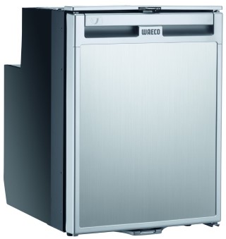
My main reason for upgrading my fridge was due to the fact I had established a very effective Solar Install. It seemed silly not to take advantage of all of that free energy to power a compressor fridge. This type of technology is far more effective than the stock fridge at doing it’s job. It actually has a dedicated freezer draw which is great for Ice Lollys on a hot day 😉 .
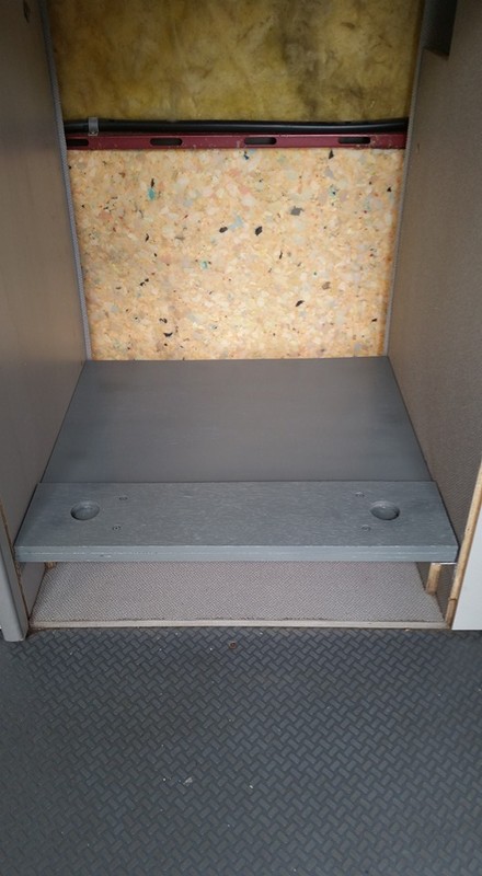
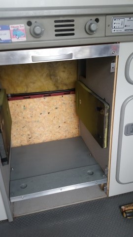
Anyways, on to the installation: I wanted this to sit just below the slide out chopping board as I wanted to maximize the depth of the draw I am going to fit below it. So after some careful measurements i set to positioning a couple of pieces of angle aluminum to sit the shelf on. The shelf was then made by two pieces of marine ply. The first was the full width and depth required to seat the fridge on. The second was a slimmer piece with two holes drilled into them where the two front feet of the fridge will locate. This will stop the fridge from sliding about as there are no real fixings as such everything is having to be bespokely made. The two pieces were glued and screwed together and painted grey.
After this i needed to find something that would provide padding either side of the fridge to wedge it in place. I wanted this to be something that wasn’t going to get affected by damp or humidity, but provide a nice gentle compression on either side of the fridge. After some time i decided that kneeling pads would be just the right depth to bridge the gap (the sort of thing you get for gardening). These cost me £1 each from Wilko . These were sprayed black at the front and they were screwed to the inside of the fridge compartment (two screws at the front and 1 at the back. each screw head had a large washer on it to pull the padding in and I tightened the screws up enough so that they sunk in and didn’t catch the fridge when being slotted in. The heads were also covered with a piece of insulation tape to be ion the safe side.
Here you can see the fridge in place:
From here on it was just about trimming the surrounding area. I brought angle aluminum from B & Q and cut and drilled to size. I had to make some bespoke brackets to mount the whole lotso it wasn’t straight forward. However, i’m pretty happy with the end result
This has then been connected directly to the leisure battery with a 5 amp fuse in line. I really need to get an additional fuse board fitted as there are way too many connectors tacked on to the battery at the moment. I will seek to have this done professionally to get things tidied up PS. There is a gap either side of the fridge of about 5mm. The finished photo here doesn’t show that and is a little miss leading. I feel this is enough of a gap to let air circulate and stop any rattles through vibrations.
My decision to change the stock 3 way fridge for a 2 way electric model meant that I would have a lot more space to take advantage of in the same space. I saw a post on social media where somebody had put in a pull out chopping board, and although it was not executed very well the idea stayed with me.
So I set to looking for the components to full fill my ambition. My wife and I went to IKEA one weekend and I saw a chopping board that was made of bamboo. I knew it would be too big for the aperture it needed to fit, but I was fully aware that I would be very lucky to find something that would fit perfectly without modification. A few days later we went to the local B & Q store to get the rest of the components.
Basic elements
Over the course of about four days I sawed drilled and screwed these items into something that looked like it would work.
Pregress
And this is the end result.
I think this will prove very useful. In a van that has very limited space, it’s things like this that will make all of the difference. Just need to get the fridge installed now. Watch this space 😉
I decided I was going to go down the Solar route late last year because the costings didn’t seem particularly expensive. On top of that I had a mounting solution available already with the Sherpas Combi Translift roof rack system so it was a bit of a no brainer really. I figured that if we can eliminate paying for electric hook-up for one year by running off batteries, we could almost re-coupe the cash spent on all of the components included (approximately £300).
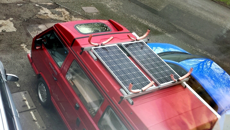
So for my birthday in November I asked for Amazon Vouchers and I got my first panel. I promptly sandwiched it between two of the four sliders on my Combi Translift. This was done using stainless fixings. 🙂
For Christmas i asked for more vouchers and got my second panel plus the Dual Battery Charger Controller and the LCD Monitor.
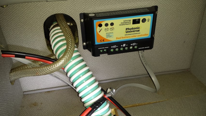
Dual Battery Charger
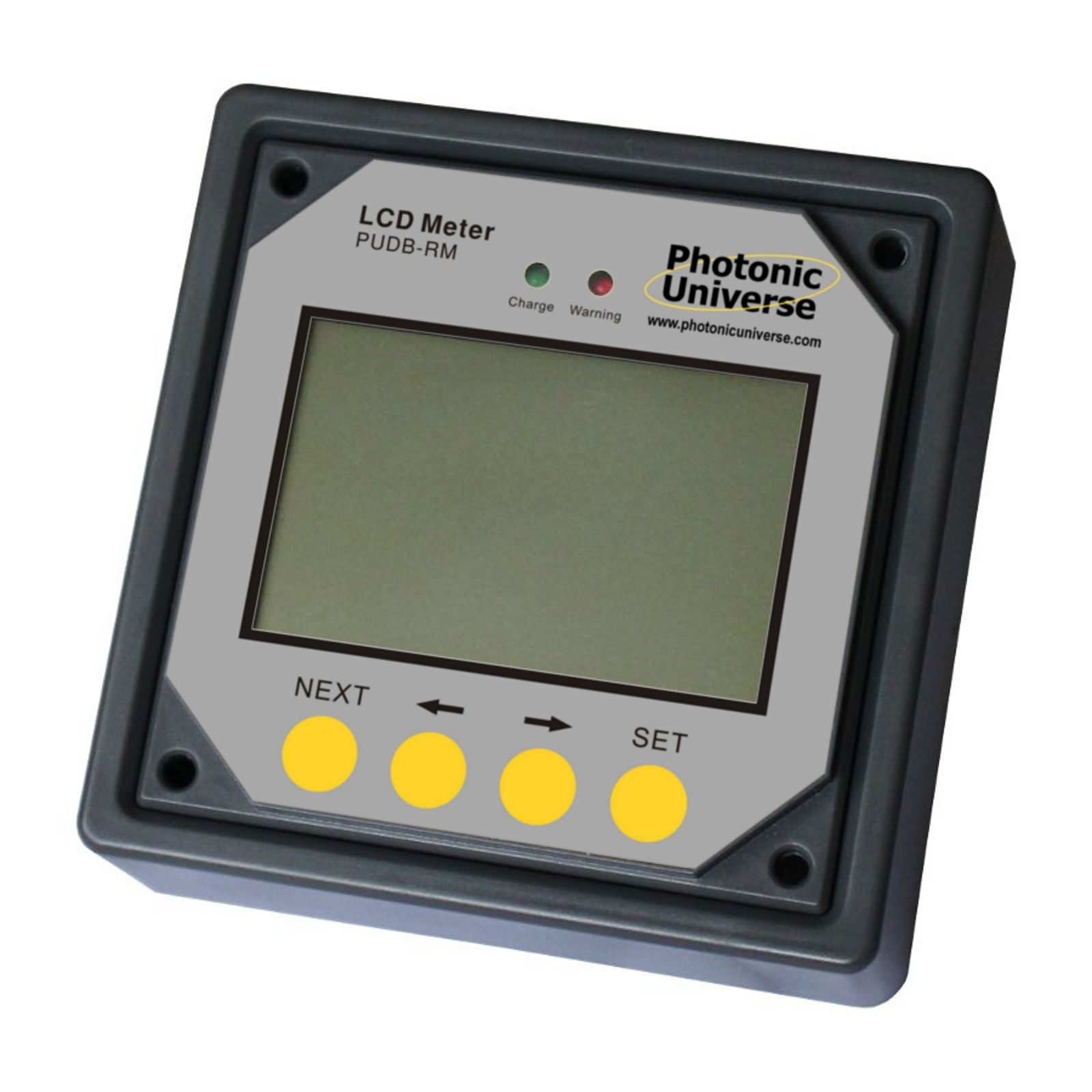
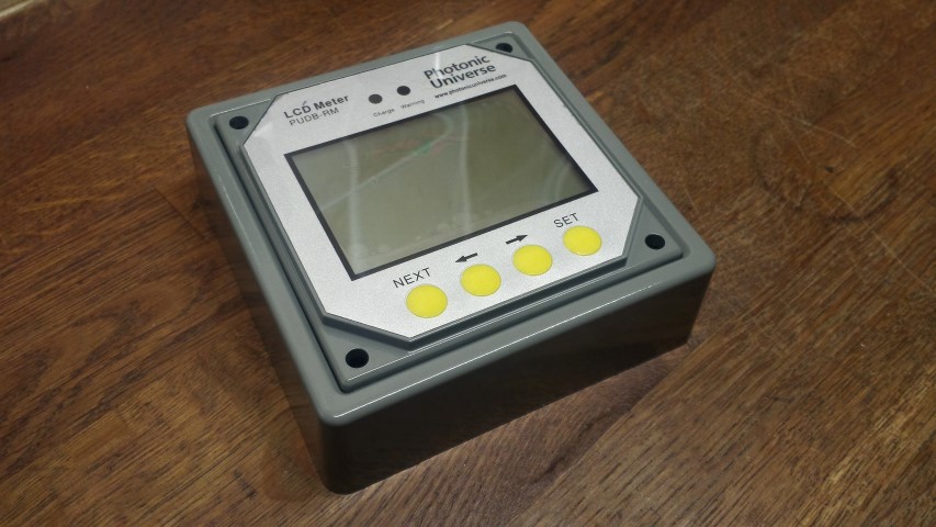
LCD Monitor
So the second panel was fitted…
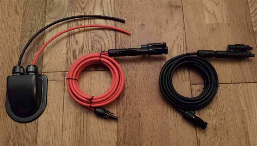
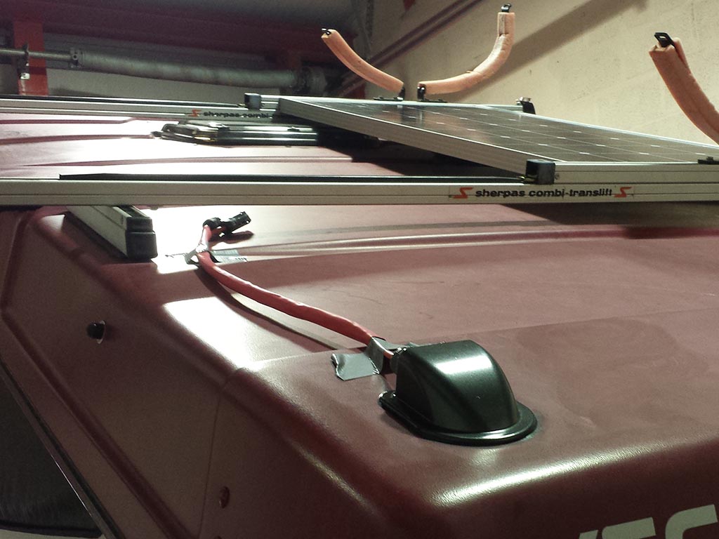
After a great deal of research I decided that the cable for my panels would be fed into the van via a cable entry gland. I found a black one that looked OK on the webpage, but when i received it I was disappointed. It was much larger than i thought and not very aesthetically pleasing. So I ended up getting a second one that was only available in white, but much smaller and less obvious. I plastic primed it and gave it a good few coats of metallic grey paint.
Cable entry gland
The only thing I was lacking now was the cables. I sourced these from eBay along with a pair of adapters that would allow both panels to hook into a single feed.
The next stage required drilling a hole in the pop top roof and mounting the cable entry gland with Sikaflex. I don’t make a habit of drilling holes in my van, but the way I looked at it was a hole drilled in the fiberglass pop top was far less intrusive than drilling a hole in the metal bodywork (which was an option I had seen done before). Each one achieves the same objective, and there is nothing to say that one way is right and the other wrong, but this is the route I decided to go down.
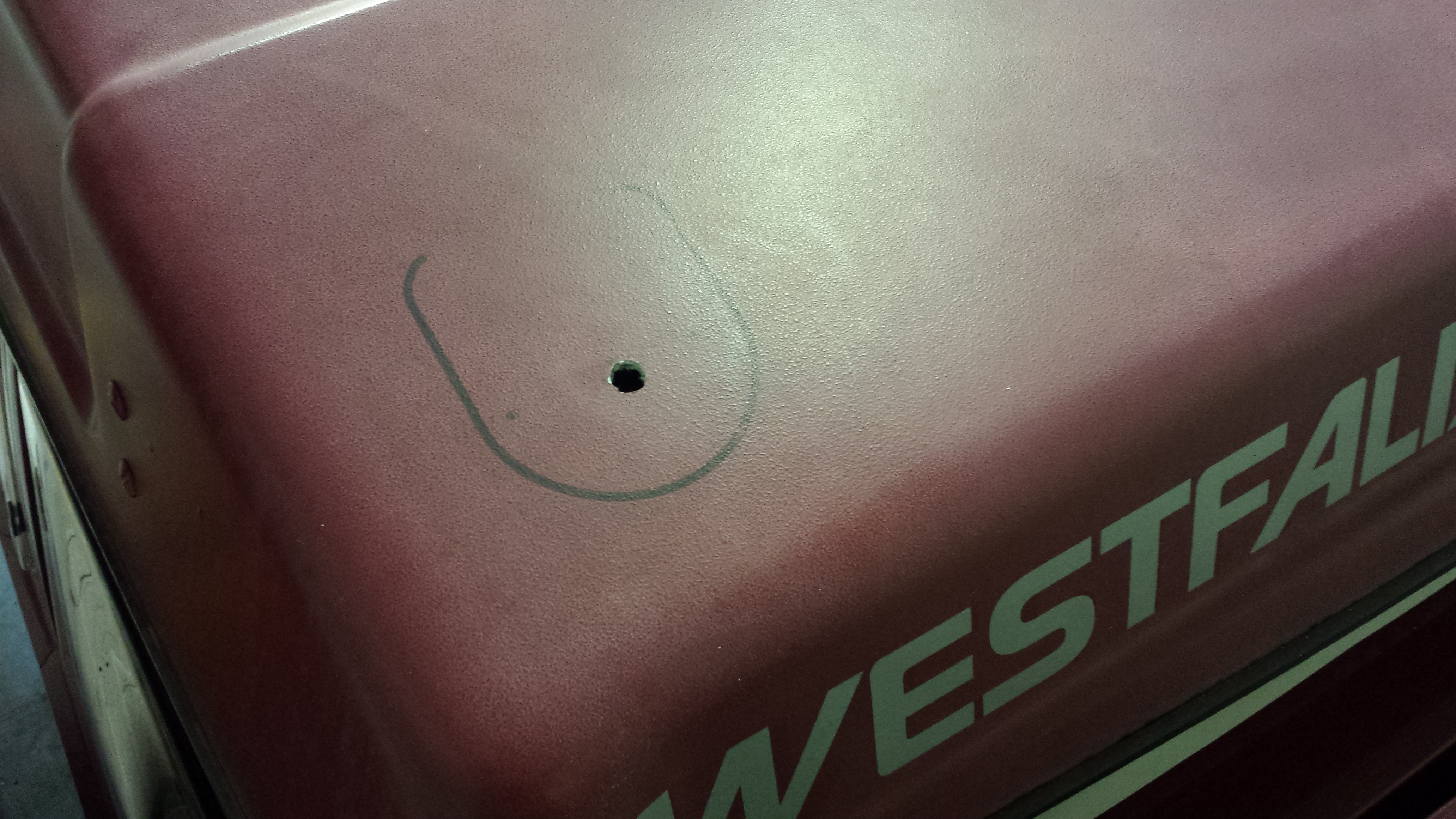
So I positioned and marked the gland on the roof for reference. Then drilled the hole.
The entry gland was positioned after feeding the cables into the aperture. And Sikaflex was used to bond it to the roof. This was held in position for a couple of hours with tape to allow time for the bonding agent to go off enough that I felt i could remove it.
So the solar cables lay coiled up on the bed in the top bunk for a month or so before i started pushing forward with the internal cabling. First job was to try and establish the best route into the wardrobe. Then drill a hole (eeek!).
Cable held down by cable clips
The cable drops into the top of the wardrobe area initially on the outside in between the rear window curtain. The com’s /data cable was just eased up along the rubber where the wardrobe front and the roof meet and follows the same path the solar cables take into the wardrobe.
Data cable for LCS Display
I made a small nick in the seal where it will rest and feed into the LCD display unit.
The unit itself came in black as pictured previously, so that’s been plastic primed and sprayed ‘industrial grey’ to more closely match the Westy interior.
Once the cables were fed into the wardrobe i needed to create a pathway to the location the solar controller would be sited. Since I decided solar would be a feature on my van I was looking constantly for information on how and where others had sited the components. The solar controller I had seen mounted in a multitude of places. These included
Inside the wardrobe – This would reduce space in an already narrow aperture and get in the way mounted higher up. Lower down this was not an option because this is used for the storage of shoes etc)
Outside the wardrobe underneath the LCD meter – This would look ugly with all of the wires feeding into the controller and would be an unnecessary eyesore (but i have seen it mounted there)
One particular location seemed better than any other. This was in one of the storage compartments next to the fridge underneath the rear table. It was deep enough that the controller would have enough room below it to accept the cables. So confident in my conviction that this was the place of all places, I set to drilling the two holes necessary to feed the cables and reach the unit. One hole was from the wardrobe to the first storage compartment above the water tank.
Feed from inside the wardrobe
Inside the first compartment
Feed into the second compartment next to fridge.
So once the cables were fed into the compartment the next thing was to mount the controller. I first placed the solar controller where i wanted it, marked the holes with a black pen and used a braddle to get the stainless self tappers to bite into the hardboard.
Solar controller mounted.
Here you can see the full run through to solar controller.
From wardrobe to cupboard
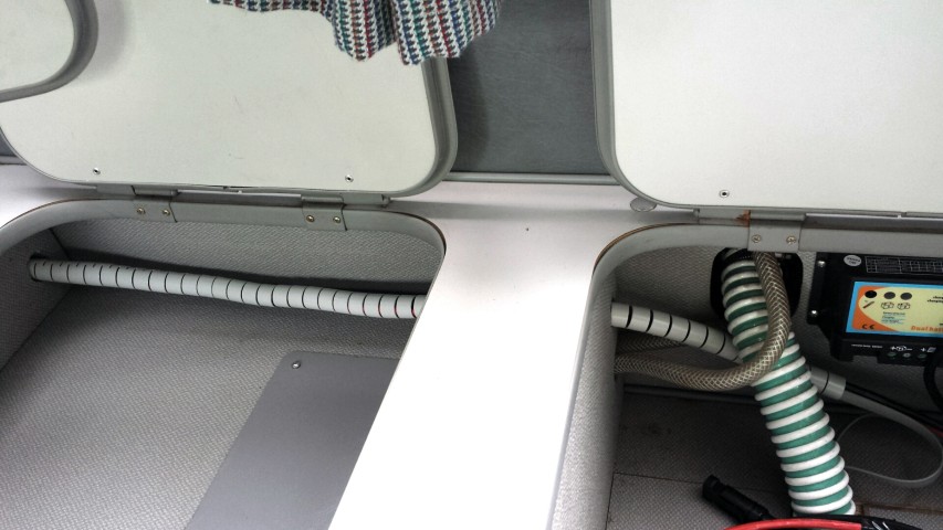
To neaten things up a little i have wrapped the cables in some cable tidy. I brought this from Maplin (UK) and was pretty pleased with the fact the colour is light grey. Far less obtrusive than black or white (although in the picture below it looks a little more obvious than it does in the flesh). The length was just right and i managed to feed all of the cables into the tidy and push it through the holes so it is one unbroken piece. It feeds all the way into the wardrobe and as far up as the outside of the wardrobe so a real neat job if i don’t say so myself. 🙂
Cables wrapped
Next I ran a two core cable from the controller to to leisure battery at the front. This was simply fed up through a gap in the unit and cable tied to the vent grid behind the cooker / draining board and sink. It then drops down into the cupboard.
Cable feed to leisure battery.
Below you can see the LCD display unit matched up in the location it will eventually sit. Not a perfect colour match but much better than the original black colour.
So the next thing to do was to wire everything together. I noticed that in the installation manual for the solar controller it states.
‘although the solar controller has built-in electronic protection, for safety and added protection please install inline fuses into the circuits between each battery and the controller, on the negative wire, as close to the batteries as possible. Current rating of fuses should be chosen according to the maximum power current / short circuit current of your solar panel’
I was a little confused because the printed installation / information manual that came with the controller also states that there should be a fuse fitted in the live from the solar panels also. So off I went to Maplin to get a couple of in line blade style fuse holders. I established that the rating of fuse i would use for both sides of the feeds would be 15amp. The short of each panel is just shy of 6amps so x 2 = 12 plus a little extra. I’m not an expert but my step dad (ex tv / radio engineer) confirmed this would be the rating i would need.
After a bit of wire stripping, soldering and heat shrink application I was all ready to connect everything. I had not gotten round to running the second battery cable to the diesel starter battery in the engine bay, but the dual battery controller will function quite happily with a single battery and does not have to have the second battery connected. Ultimately I want to get the starter battery connected. The charge from the controller can be split between the two batteries by percentage. I am thinking a 20% charge to the starter and the rest going to the leisure battery (house for those in the US) should work quite well for prolonged periods being static. This should maintain a few amps to keep enough charge in the starter battery to make sure we don’t get stuck, but the majority of the power will be diverted to the living area for TV, radio, phone / tablet charging and interior lights.
So here is the final install with the controller / LCD meter connected.
Controller Wired up
The only setting I had to change on the solar controller was to the battery type which should be set to Type 3 for ‘Flooded’ (Lead acid) battery. The other options are AMG and sealed (I think?).
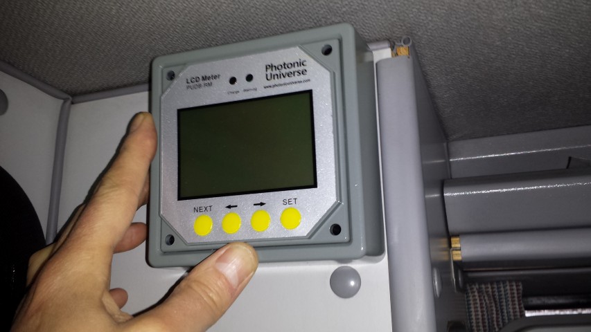
LCD Display
Here you can see the LCD controller connected. I fixed it to the wardrobe unit using double sided foam pads. Having fed the data cable over the wardrobe top the flat cable was very tight and forced the face front out and away from the units. The low profile of double sided tape would have made everything tight and probably wouldn’t have given the extra couple of mm required to mount. However, the double sided foam allowed that extra distance to mount. It does tend to rock a fraction when the buttons are pressed as the foam gives a little, but this is livable and far better than drilling and self tapping the display into the wardrobe unit. I’ts pretty secure and certainly isn’t going anywhere in a hurry (*See amendment at bottom of page). Also, it’s a novelty now so I am having a play and seeing what does what, but I am sure I will settle on a particular screen that will give me the information I feel most appropriate and leave it set to that….in time 🙂
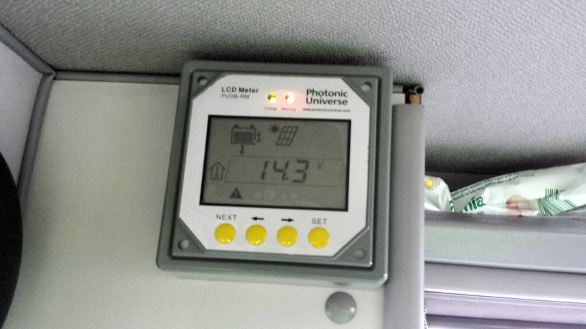
You can see two lights on the display. One is green showing that the panels are charging 🙂 , the second is red showing a warning 🙁 . The annoying thing is that the warning is just to show that the second battery isn’t attached. As said previously the controller functions perfectly well without a second battery, but there is no way of acknowledging you are happy with one battery to remove the warning. Anyways, all in all I have a working system so win, win 🙂
LCD Display Illuminated
UPDATE
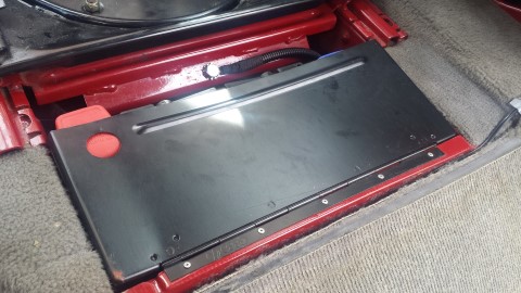
It seemed a shame to have all of this available power, yet only a single leisure battery to save it to. So my next job was to source a suitable battery that would fit in the compartment behind the right hand (passenger) seat. This would be linked directly to the first battery giving a larger source of power to draw from. The one I chose was advertised as a T25 battery on ebay and is branded Xplorer. The seller is alpha_man_batteries. This battery combined with my existing would give me a total of 180ah 🙂
I decided I would get this done by an auto electrician as it would involve feeding cables under the van and i preferred it to be done correctly. I did mention to him that if he had time that he try and route a cable from the solar controller to the starter battery in the engine compartment. I had quite recently been made aware that the interior lights run off this battery and i was mindful that this would reduce the chance of finding myself in a position where i could not start my van should too much power be used. It was at this point I also made the decision to change my fluorescent interior light for LED (Guide here LED interior light upgrade)
After two days I collected my van and was really happy with the work he had done fitting the leisure battery. As an added bonus he had managed to route the cable from controller to starter battery. This is the leisure battery. As you can see it’s snug but not not too obvious when the compartment door is closed.
Battery
Door only slightly proud
Door only slightly proud
Here you can see where the black cable for the starter battery enters the wardrobe (right) , and feeds through a hole he drilled in the floor, which in turn is fed into the engine bay and round to the battery. The hole was sikaflexed to stop water ingress.
Routing of cable in wardrobe from solar controller to battery
Below you can see that the LED solar display is now showing two batteries connected and the red error / warning light has gone out 🙂
Well that’s pretty much my solar install from start to finish. I hope this has been useful and if anybody needs any more information please leave a comment and i will message back accordingly 🙂
Andy
*Amendment
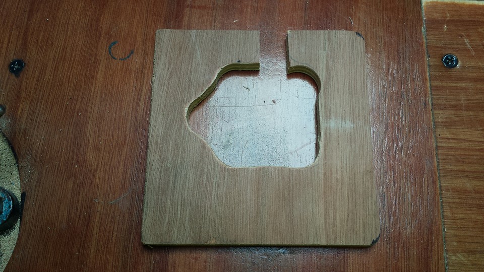
Although the LCD controller appeared to stick to the units like glue with the foam sticky pads, I think the change in temperature on hot days \ cool nights was enough to upset it enough and it kept coming away leaving it hanging from the data cable. I realized that the surface area of the small foam pads on the thin outer edge of the display molding wasn’t enough to keep it in place. This got really frustrating so i set to concocting a more permanent fix. This consisted of a piece of ply board cut to shape and painted grey to match the interior of the van.
Cut Ply Board
Painted Grey
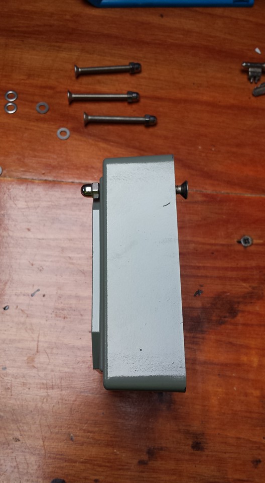
Four holes were drilled in the board to match up with the holes in the LCD display unit. I brought 4 stainless countersunk head screws which were fed in from the bach of the ply board, through the display and tightened up. The strange shape hole cut in the ply allowed the data cable to feed out of the back. The controller has a much greater contact area at the rear of the display for double sided adhesive tape, and as a result has stayed firmly in place since mounted. Result 🙂









 . These were sprayed black at the front and they were screwed to the inside of the fridge compartment (two screws at the front and 1 at the back. each screw head had a large washer on it to pull the padding in and I tightened the screws up enough so that they sunk in and didn’t catch the fridge when being slotted in. The heads were also covered with a piece of insulation tape to be ion the safe side.