My decision to change the stock 3 way fridge for a 2 way electric model meant that I would have a lot more space to take advantage of in the same space. I saw a post on social media where somebody had put in a pull out chopping board, and although it was not executed very well the idea stayed with me.
So I set to looking for the components to full fill my ambition. My wife and I went to IKEA one weekend and I saw a chopping board that was made of bamboo. I knew it would be too big for the aperture it needed to fit, but I was fully aware that I would be very lucky to find something that would fit perfectly without modification. A few days later we went to the local B & Q store to get the rest of the components.
Basic elements
Over the course of about four days I sawed drilled and screwed these items into something that looked like it would work.
Pregress
And this is the end result.
I think this will prove very useful. In a van that has very limited space, it’s things like this that will make all of the difference. Just need to get the fridge installed now. Watch this space 😉
I decided to take my van to Brickwerks for a service some 6 months or so after buying it back in May 2015. I’m a bit precious about my vehicles and have found myself in a situation on numerous occasions in the past not really trusting the run of the mill, modern car garage. So the first visit was for one day which included a service, inspection and a fix of anything that was clearly not right and fixable within the constraints of the day. So from there we had a list. One year on and my van was in for a minor service to follow on from the full one in 2015, and a brief to chip away at the already identified issues. All good in the hood….Not quite!
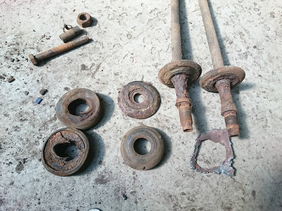
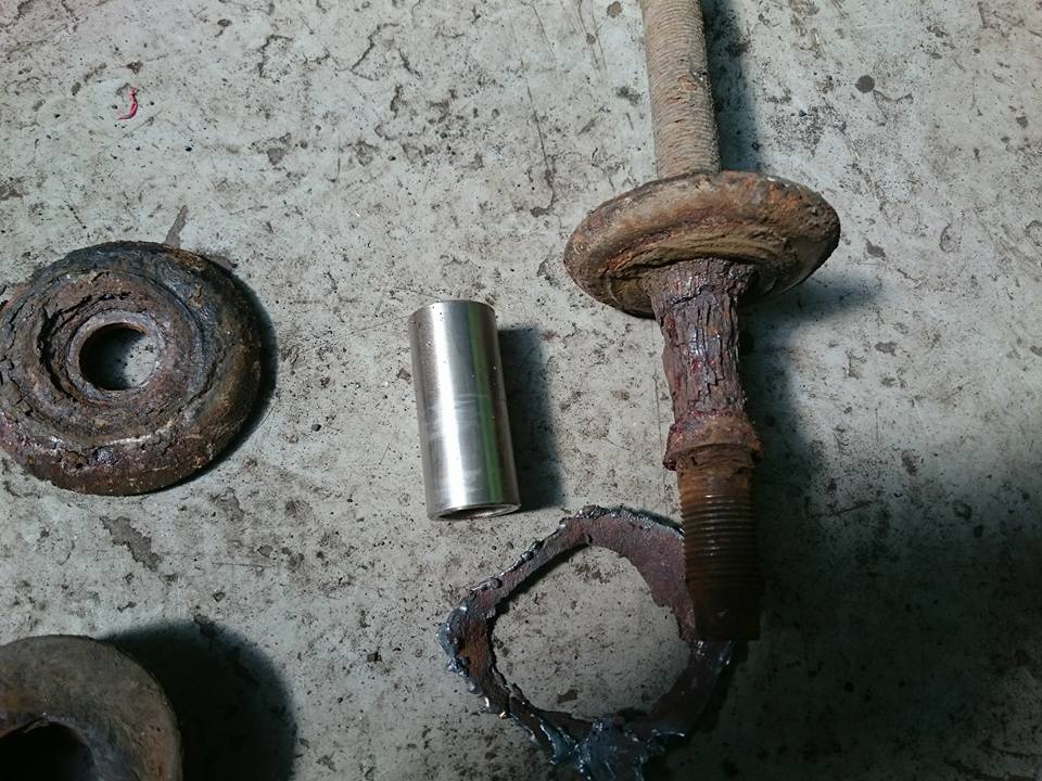
It soon became apparent that I had some quite serious issues as a result a distinct lack of maintenance by the previous owners. Radius arm bushes were identified as being perished on the first visit, and although this on it’s own is not uncommon, the fact that after further investigation it was quite conceivable that none of the associated components had ever had any maintenance since it left the factory in 1990.
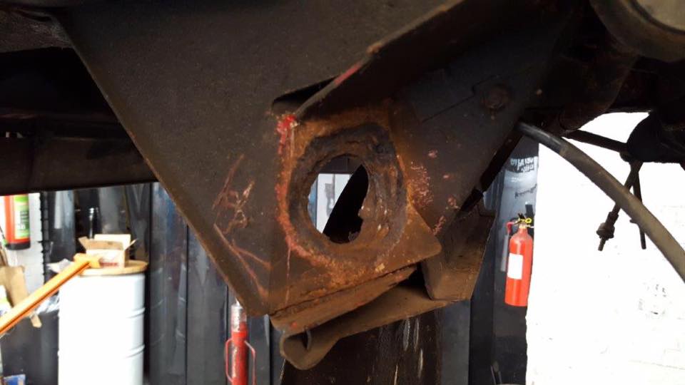
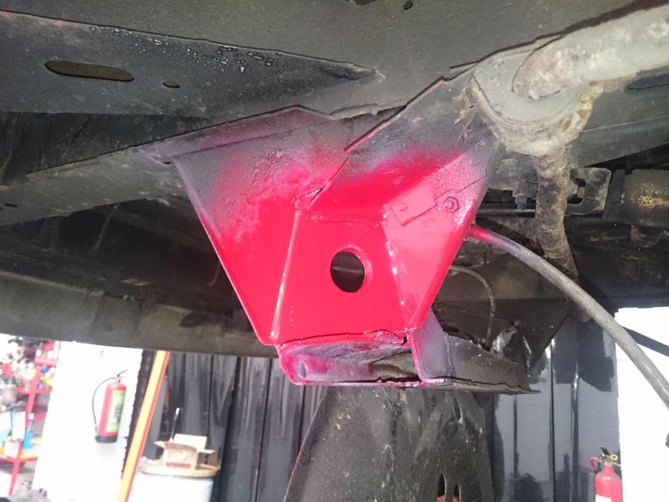
Radius arm and perished bushesMassively damaged body mount aperture
After viewing these parts it dawned on me that if these issues hadn’t been identified during this visit, structural failure was going to happen at some point in the not too distant future. I’m not complaining, but this unforeseen issue was now at the forefront of my vans visit to Brickwerks.
The following is pretty much a step by step pictorial of how the repair was done. I will hasten to add that there is a lot more science and expertises to this than just being able to use a welder and a grinder. If you care about your van…and more importantly the occupants, pedestrians and other road users that may become involved as a result of dodgy workmanship, i would recommend you leave this sort of fix to the experts.
So the first pictures were emailed to me by Simon at Brickwerks (above). This was great as I was left in no doubt that this really needed addressing. Shortly after followed these showing the progress:
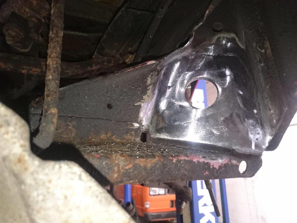
All corrosion cut out of the ‘three’ affected layers.
First layer of plate welded in from the back, after which the middle and front followed.
All visible surfaces were cleaned back and the hole was drilled for the radius arm. I will say that this hole was not guess work. A template was made from a new off the shelf part to make sure it was in exactly the right place.
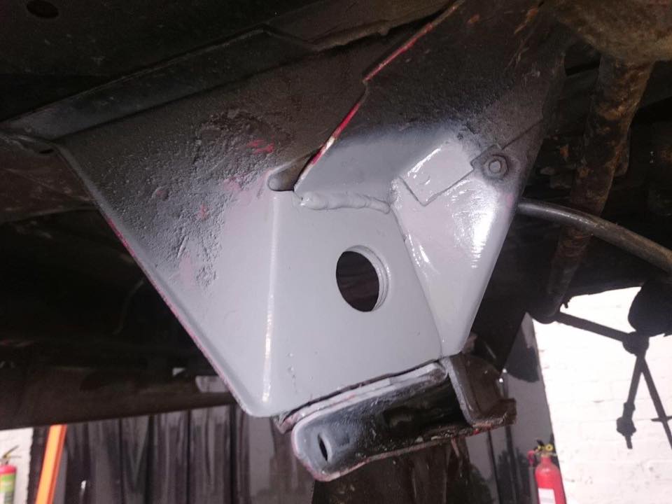
After this the bare metal was primed…
Painted…
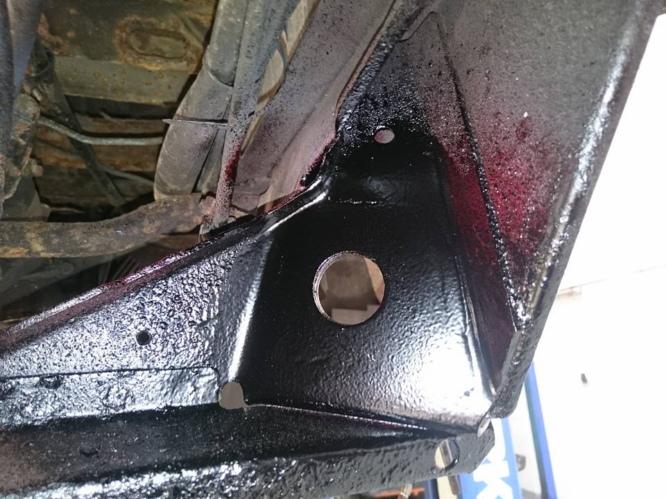
and Dinitrol applied to stop stone chips & water ingress.
I’ll just point out that the above photo shows one of the desperately thing layers of metal that made up a part of the chassis connector points. The repair (I think you will agree) is a million miles away from the old and worn out parts that were on my van when I purchased it.
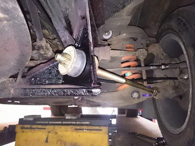
So this is the finished article….
Note: When I first got my van I went through a process of replacing some of the suspension parts such as coil springs and dampers. This improved the ride of the van massively and I didn’t think it could get any better. I was proven wrong and it was instantly noticeable on the way back to Derby from the workshop in Yorkshire that it was so much tighter on the bends and bumps. This just goes to show that it is a sum of all of the components being in good working order that makes a van handle well.
This issue was identified during a visit to Brickwerks for a service and maintenance. The repair for this was done at the same time as the work done on the radius arms.
The culprit. Old and worn due to a distinct lack of maintenance.
Westy Specific (but may help owners of other conversions)
My reason for replacing the original fluorescent tubes for LED was purely down to the fact i had completed my solar install and wanted to increase my efficiency and reduce my ties to electric hookup. I had previously brought a 300mm LED light to test the water last year. This was unbranded and didn’t claim to be warm lighting. I didn’t mind at the time because the way I saw it i could use the one light when off grid to reduce the power we were using. However the tube was very bright to the point where we didn’t really want to use it unless we had to. Since i brought my van, and time has gone on, i can certainly see the benefit to the ‘warm glow’ LED lights.
All of that said, the one LED i had installed above my sliding door was still fitted with the ballast controller designed to start the old fluorescent tube. This decreased the efficiency & brightness of the LED light. So after receiving my new tubes from Campervan Culture, i saw the advisory note on the packaging to bypass the ballast. So I started to strip down the light unit and tried figure out what this meant. After a dismally failed attempt at getting the wiring right i decided to create a user guide for the Westy owner that may want to complete this modification. This may be helpful to owners of other conversions, but i can’t say for sure. I would imagine the basics are the same.
The first thing to do was to isolate the power supply by detaching your battery. As standard these lights run off the starter battery so that’s the one you need to detach. (Note: Modifications can be made to run these lights off the leisure battery so bear this in mind if you find your lights are still working after detaching the engine starter battery). After this you can go ahead and remove the light unit from the ducting.
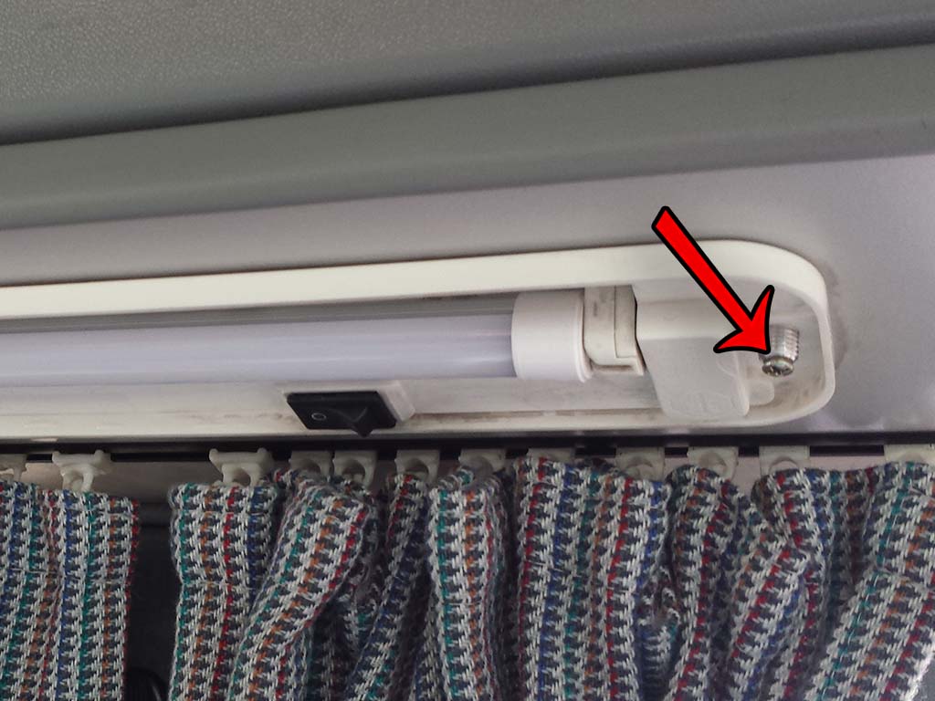
There are three lights in total. One is above the sliding door and the other two are on the opposite side above the cooker and rear table. All are unscrewed in the same way. Firstly the two black knurled plastic lugs are removed with a flat bladed screwdriver. This allows the clear lens to drop out. This also gives access to a cross head self tapping screw pictured below. Remove these whilst supporting the light.
The light on the right hand side above the sliding door can be disconnected by detaching a couple of spade connectors. Unfortunately the two on the left of the van reveal no such connectors. So for these two the cables must be cut to remove.
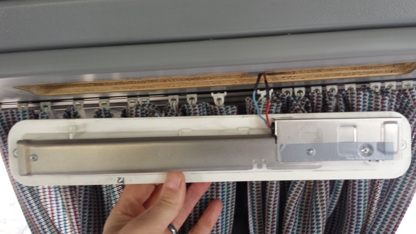
So this is the back of the light on the work bench. It soon becomes apparent that there is no way of progressing this without removing the pop rivets that hold the unit together. I did this using a pillar drill. However, a suitable workbench and careful use of a drill should suffice.
You can get away with drilling out only the three rivets pictured above. The two outer rivets will enable you to remove the ballast enclosure from the lamp, and the center pot rivet secures a transistor to the aluminum housing. Use a drill bit to take off the head off each rivet being careful not to drill too deep. Once this is done the whole of the ballast unit should be able to be removed far enough away to use a bradle or small gauge screw driver to push out the rivet body and release the aluminum from the ballast electronics.
Next detach all of the wires that connect the PCB ballast to the wires using a soldering iron! So this is what we have removed …..
Ballast Electronics
I will say at this point that i did actually drill out the last remaining rivet holding on the long aluminum strip covering the long wires, so the images below reflect this and may not represent what you see. It allows you to see the wiring a little more clearly in this guide. I would recommend leaving it in place.
Image 1
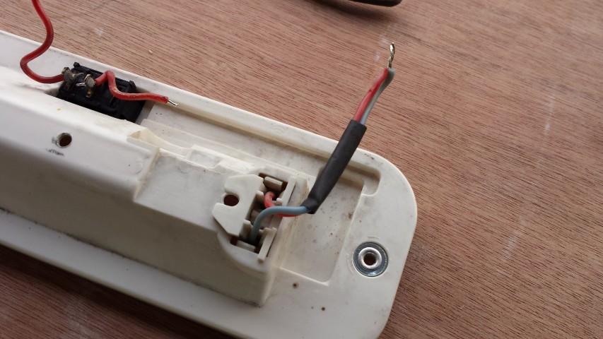
The rest of the guide is just a case of taking what we are left with and putting it all back together in a way that works with the new tube. Ignore the color coding of the wiring from now on. Basically we need to provide a positive and negative connection to each side of the new tube / bulb. Using the wires we have de-soldered from the ballast, strip back the insulation on the two longest wires by approximately 1cm so there is enough wire visible so you can twist them together. Solder them together and then solder the spare light blue wire onto them in turn. Cover the join with heat shrink. This can be seen in the picture above (the long cable in the lower half of Image 1.)
Image 2
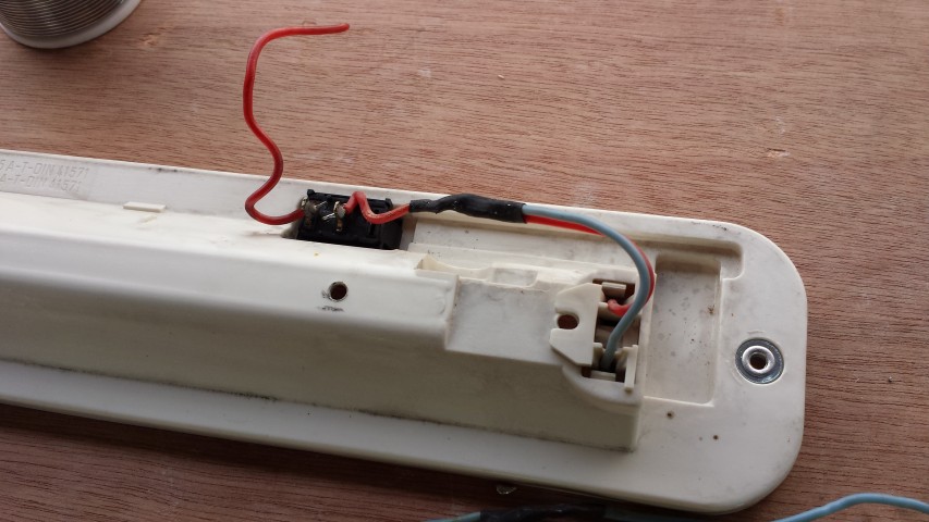
Next do the same to the opposite end. Strip the wires back, twist together and solder (Image 2). After this connect these two wires to the on / off switch and heat shrink to insulate the connection (Image 3).
Image 3
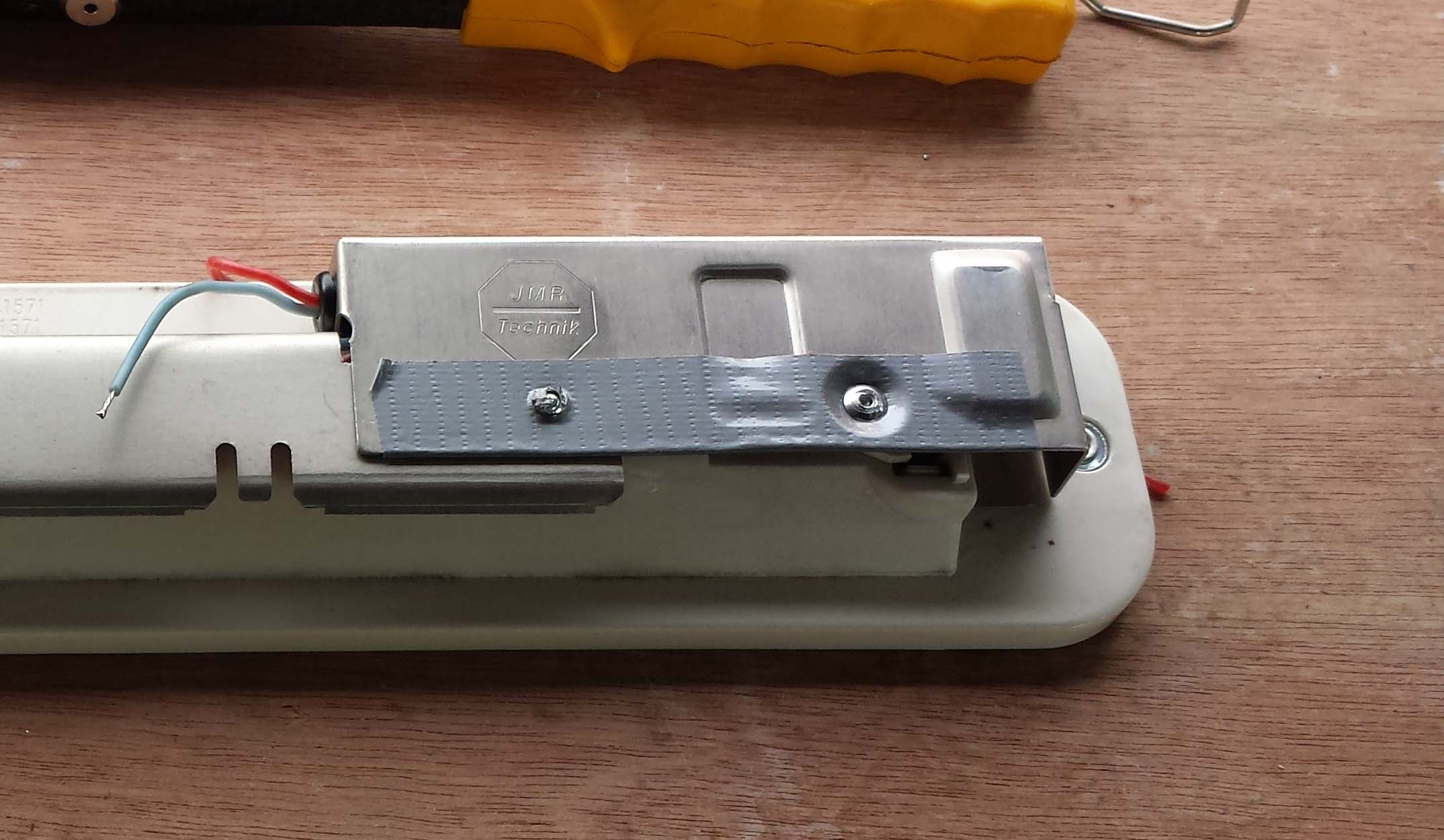
The jury is out as to which way you go with this next part. I don’t actually think this is really necessary to re-attach the aluminum box that contained the ballast electronics as there is really nothing left to protect. However, i decided it was going back on if for no other reason than to keep the cables from getting trapped between the lamp and the ducting whilst fixing to the van. Taping in place would achieve the same objective i guess but for the sake of a couple of rivets I chose to fit the casing. I covered the inside of the aluminum with insulation tape just to be on the safe side to stop the wiring on the switch from shorting out on the metalwork (belt and braces). I used a braddle to create the two holes in the insulation for the pop rivets.
Insulation
Next i found appropriate sized pop rivets from my multi pack collection brought from ALDI . I will try and establish which sizes i used where, and feed back. So the below image shows the cover connected after feeding the positive and negative feeds through the small hole with the grommet.
Close up
So the unit it basically built up and should work with your new LED tube. Just re-connect to the wires in your van using solder and heat shrink…If the bulb does not work turn it over and re-insert. LED’s will only work in one direction.
and screw back in place
The lights should use less power than before and be slightly brighter as a result of loosing the ballast. 😉 .
I saw these kits a few months back and thought they looked pretty cool. These backlit gauge kits are fitted over the original gauges to bring the clock bang up to date. The purchase of a Porche steering wheel made me think that this could be the kit i needed to go the whole hog and change the driving feel of the van. Still not 100% sure about the steering wheel as I haven’t gotten round to fitting it yet, but I’m pretty chuffed with the gauge kit (photos to come)
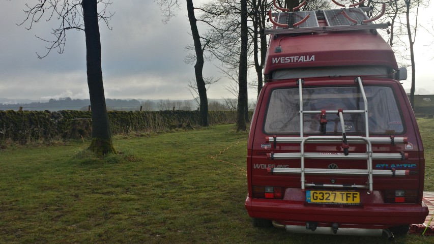
This was a nice little break just before the Easter Bank Holiday. We left it too late to book anywhere for the Easter weekend so when this became apparent I managed to arrange two days off work at short notice. We didn’t want to be travelling far and a 1 hour (35 mile drive) proved perfect. I finished work at 5pm and drove home to collect Mandy. We got to the campsite just before 7pm and were all set up with the heater on by 7.15. It was overcast and dark by this point.
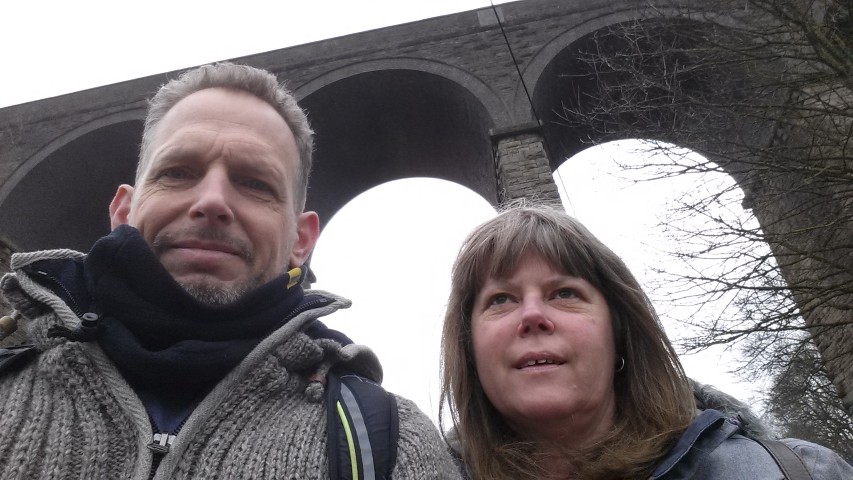
The following day was cool and still overcast but we wrapped up and headed into Buxton taking the scenic route on foot.
Dukes Drive Train Bridge
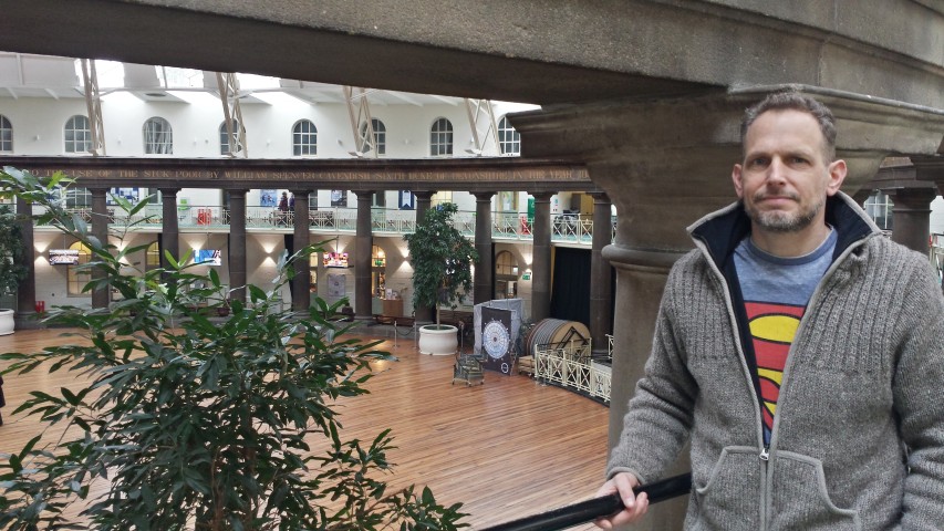
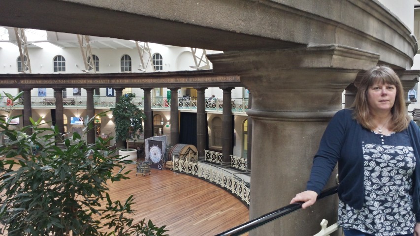
We had a wander for a couple of hours and then had a bite to eat at Pizza Express before heading off to the old Royal Devonshire Hospital, now the University Of Derby’s hospitality and catering section. This was of particular interest to me as I had been lucky enough to visit it in it’s dilapidated state before the funding had been raised to renovate it into what it is today. I was commissioned to do a 3D fly through to help prospective funders visualize and ultimately donate money to what would be a very worthy cause.
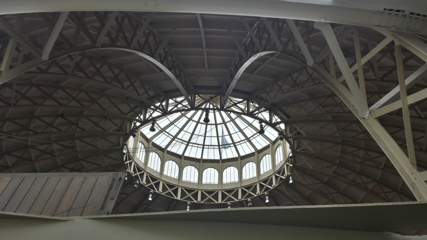
Warming myself in the domeThe ‘Dome’. Larger than St Paul’s!Mandy
Anyways, we both got back to the camp site and slept well after all of the exercise. I knew by the forecast that the weather would break on Thursday so fully anticipated a lazy day in the van reading books, listening to the radio and watching TV. All very good as the views were amazing 🙂
Good Friday we had an appointment at my brothers for lunch, so after a coffee and breakfast we headed back to Derby. What a great few days. But any time in the van is good time 🙂
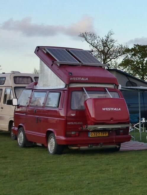
This show was just about as local as you could get so no excuses! 🙂 It was at Shardlow Marina and approximately 70 vans turned up. Just a Friday and Saturday night camp over.
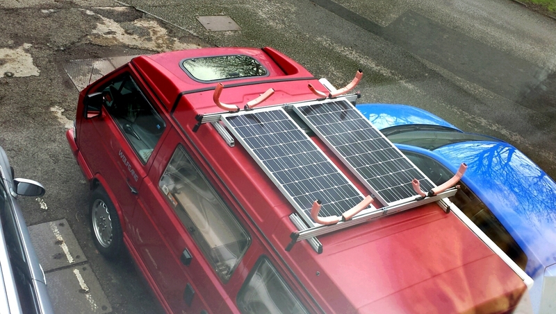
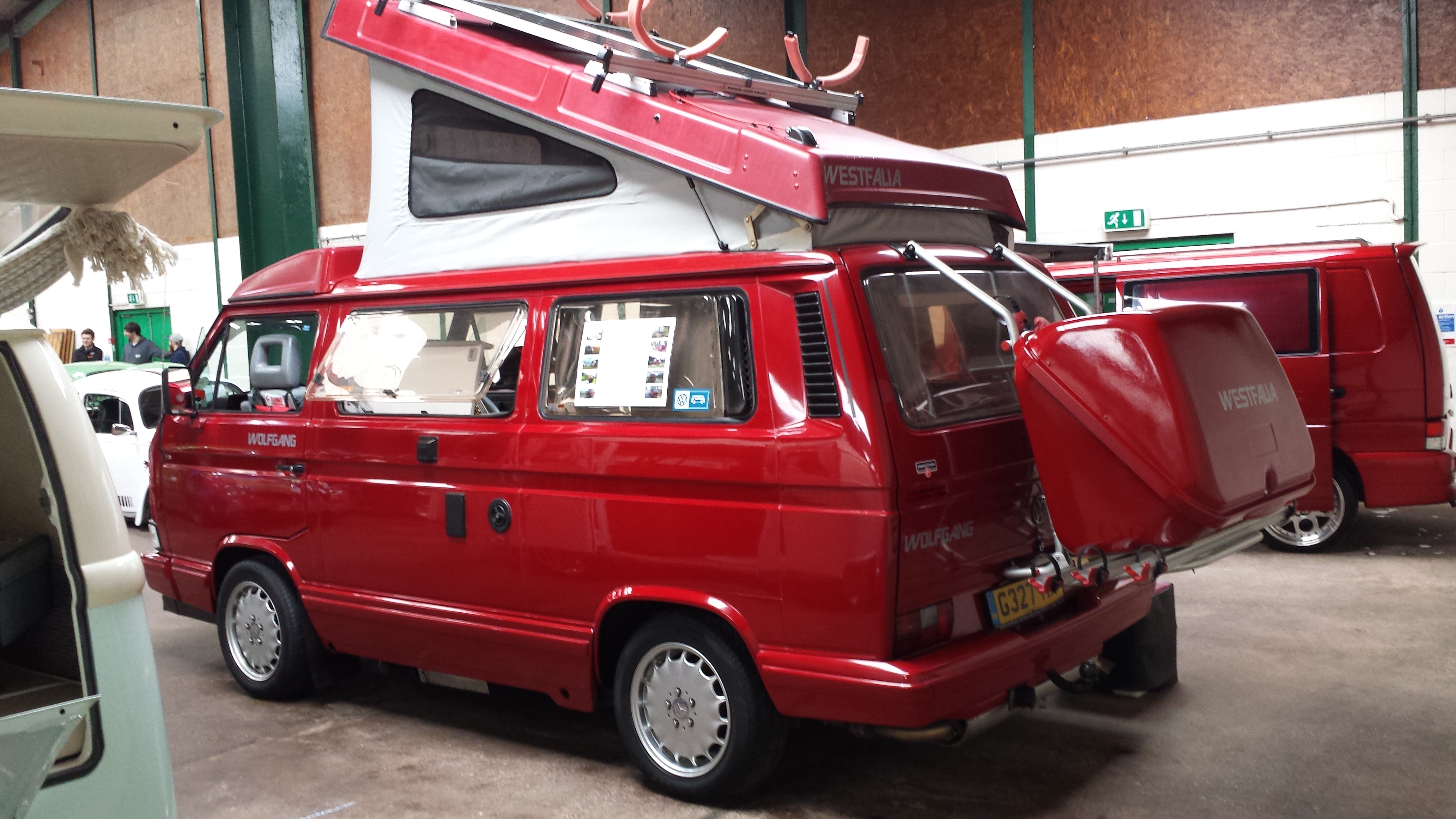
I decided I was going to go down the Solar route late last year because the costings didn’t seem particularly expensive. On top of that I had a mounting solution available already with the Sherpas Combi Translift roof rack system so it was a bit of a no brainer really. I figured that if we can eliminate paying for electric hook-up for one year by running off batteries, we could almost re-coupe the cash spent on all of the components included (approximately £300).
So for my birthday in November I asked for Amazon Vouchers and I got my first panel. I promptly sandwiched it between two of the four sliders on my Combi Translift. This was done using stainless fixings. 🙂
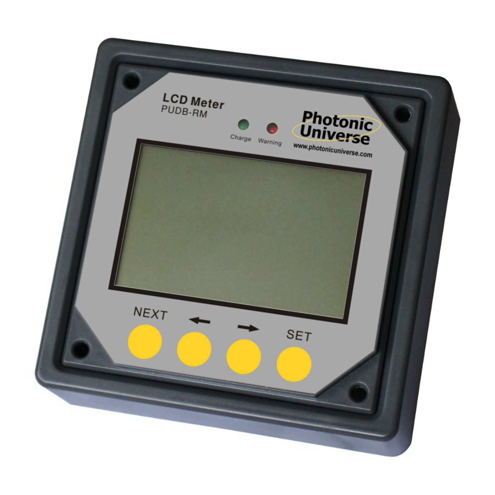
For Christmas i asked for more vouchers and got my second panel plus the Dual Battery Charger Controller and the LCD Monitor.
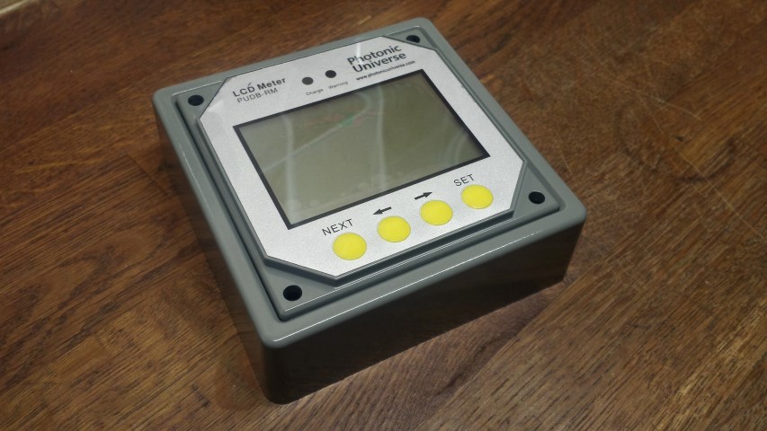
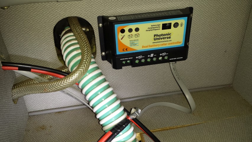
Dual Battery ChargerLCD Monitor
So the second panel was fitted…
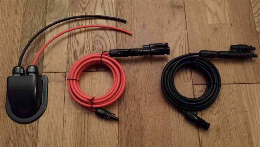
After a great deal of research I decided that the cable for my panels would be fed into the van via a cable entry gland. I found a black one that looked OK on the webpage, but when i received it I was disappointed. It was much larger than i thought and not very aesthetically pleasing. So I ended up getting a second one that was only available in white, but much smaller and less obvious. I plastic primed it and gave it a good few coats of metallic grey paint.
Cable entry gland
The only thing I was lacking now was the cables. I sourced these from eBay along with a pair of adapters that would allow both panels to hook into a single feed.
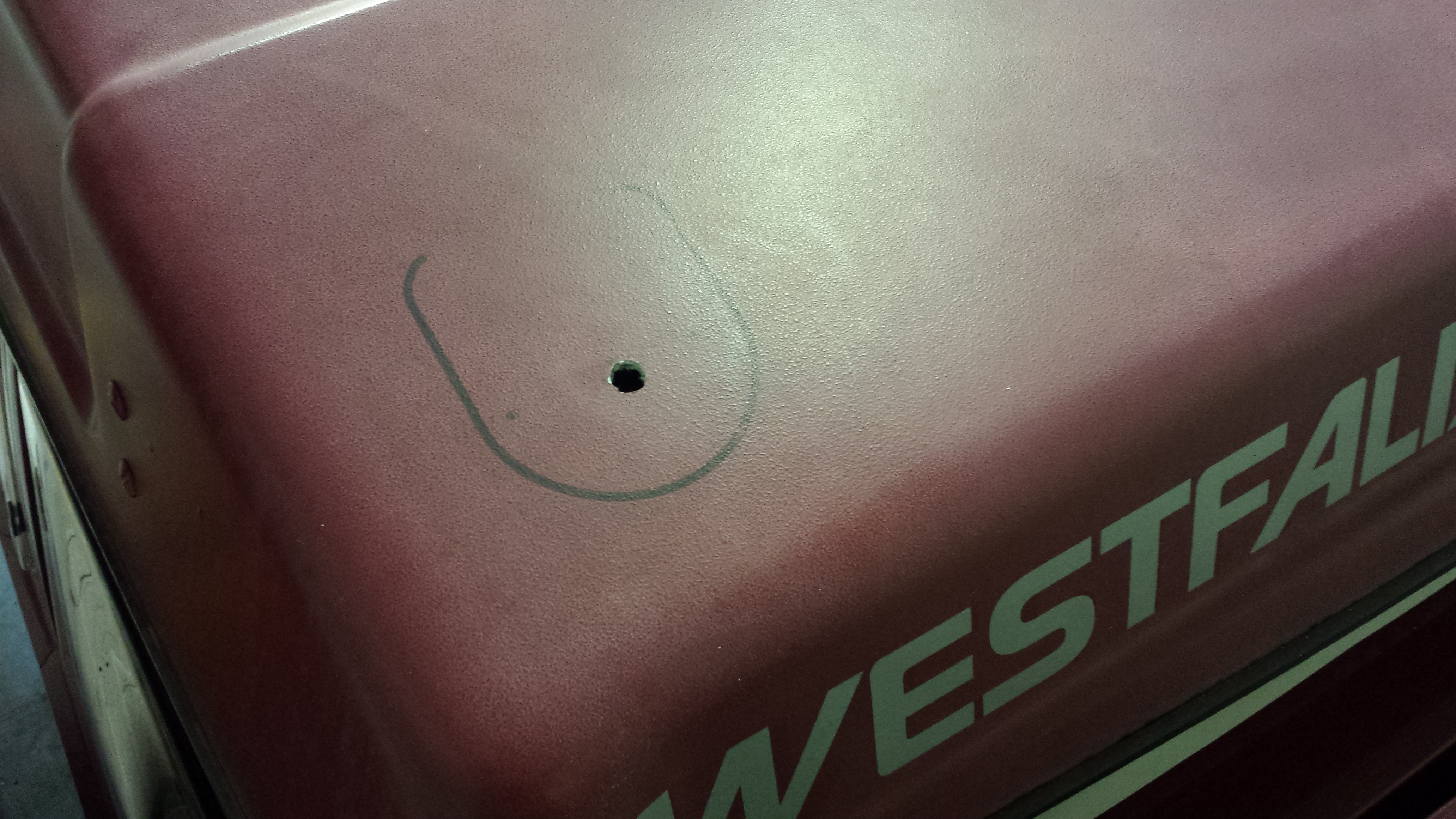
The next stage required drilling a hole in the pop top roof and mounting the cable entry gland with Sikaflex. I don’t make a habit of drilling holes in my van, but the way I looked at it was a hole drilled in the fiberglass pop top was far less intrusive than drilling a hole in the metal bodywork (which was an option I had seen done before). Each one achieves the same objective, and there is nothing to say that one way is right and the other wrong, but this is the route I decided to go down.
So I positioned and marked the gland on the roof for reference. Then drilled the hole.
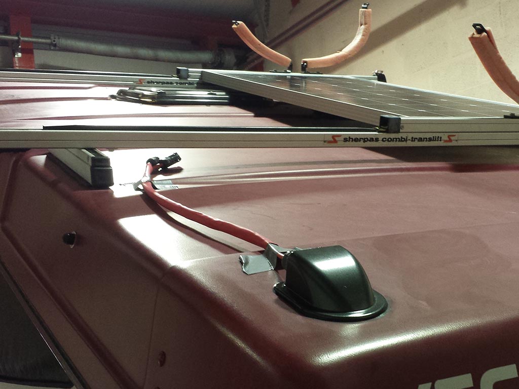
The entry gland was positioned after feeding the cables into the aperture. And Sikaflex was used to bond it to the roof. This was held in position for a couple of hours with tape to allow time for the bonding agent to go off enough that I felt i could remove it.
So the solar cables lay coiled up on the bed in the top bunk for a month or so before i started pushing forward with the internal cabling. First job was to try and establish the best route into the wardrobe. Then drill a hole (eeek!).
Cable held down by cable clips
The cable drops into the top of the wardrobe area initially on the outside in between the rear window curtain. The com’s /data cable was just eased up along the rubber where the wardrobe front and the roof meet and follows the same path the solar cables take into the wardrobe.
Data cable for LCS Display
I made a small nick in the seal where it will rest and feed into the LCD display unit.
The unit itself came in black as pictured previously, so that’s been plastic primed and sprayed ‘industrial grey’ to more closely match the Westy interior.
Once the cables were fed into the wardrobe i needed to create a pathway to the location the solar controller would be sited. Since I decided solar would be a feature on my van I was looking constantly for information on how and where others had sited the components. The solar controller I had seen mounted in a multitude of places. These included
Inside the wardrobe – This would reduce space in an already narrow aperture and get in the way mounted higher up. Lower down this was not an option because this is used for the storage of shoes etc)
Outside the wardrobe underneath the LCD meter – This would look ugly with all of the wires feeding into the controller and would be an unnecessary eyesore (but i have seen it mounted there)
One particular location seemed better than any other. This was in one of the storage compartments next to the fridge underneath the rear table. It was deep enough that the controller would have enough room below it to accept the cables. So confident in my conviction that this was the place of all places, I set to drilling the two holes necessary to feed the cables and reach the unit. One hole was from the wardrobe to the first storage compartment above the water tank.
Feed from inside the wardrobeInside the first compartmentFeed into the second compartment next to fridge.
So once the cables were fed into the compartment the next thing was to mount the controller. I first placed the solar controller where i wanted it, marked the holes with a black pen and used a braddle to get the stainless self tappers to bite into the hardboard.
Solar controller mounted.
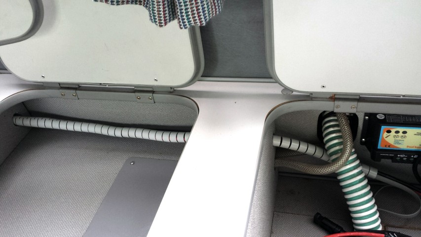
Here you can see the full run through to solar controller.
From wardrobe to cupboard
To neaten things up a little i have wrapped the cables in some cable tidy. I brought this from Maplin (UK) and was pretty pleased with the fact the colour is light grey. Far less obtrusive than black or white (although in the picture below it looks a little more obvious than it does in the flesh). The length was just right and i managed to feed all of the cables into the tidy and push it through the holes so it is one unbroken piece. It feeds all the way into the wardrobe and as far up as the outside of the wardrobe so a real neat job if i don’t say so myself. 🙂
Cables wrapped
Next I ran a two core cable from the controller to to leisure battery at the front. This was simply fed up through a gap in the unit and cable tied to the vent grid behind the cooker / draining board and sink. It then drops down into the cupboard.
Cable feed to leisure battery.
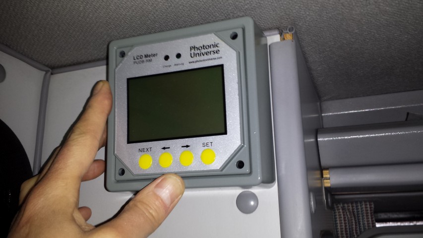
Below you can see the LCD display unit matched up in the location it will eventually sit. Not a perfect colour match but much better than the original black colour.
So the next thing to do was to wire everything together. I noticed that in the installation manual for the solar controller it states.
‘although the solar controller has built-in electronic protection, for safety and added protection please install inline fuses into the circuits between each battery and the controller, on the negative wire, as close to the batteries as possible. Current rating of fuses should be chosen according to the maximum power current / short circuit current of your solar panel’
I was a little confused because the printed installation / information manual that came with the controller also states that there should be a fuse fitted in the live from the solar panels also. So off I went to Maplin to get a couple of in line blade style fuse holders. I established that the rating of fuse i would use for both sides of the feeds would be 15amp. The short of each panel is just shy of 6amps so x 2 = 12 plus a little extra. I’m not an expert but my step dad (ex tv / radio engineer) confirmed this would be the rating i would need.
After a bit of wire stripping, soldering and heat shrink application I was all ready to connect everything. I had not gotten round to running the second battery cable to the diesel starter battery in the engine bay, but the dual battery controller will function quite happily with a single battery and does not have to have the second battery connected. Ultimately I want to get the starter battery connected. The charge from the controller can be split between the two batteries by percentage. I am thinking a 20% charge to the starter and the rest going to the leisure battery (house for those in the US) should work quite well for prolonged periods being static. This should maintain a few amps to keep enough charge in the starter battery to make sure we don’t get stuck, but the majority of the power will be diverted to the living area for TV, radio, phone / tablet charging and interior lights.
So here is the final install with the controller / LCD meter connected.
Controller Wired up
The only setting I had to change on the solar controller was to the battery type which should be set to Type 3 for ‘Flooded’ (Lead acid) battery. The other options are AMG and sealed (I think?).
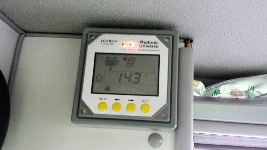
LCD Display
Here you can see the LCD controller connected. I fixed it to the wardrobe unit using double sided foam pads. Having fed the data cable over the wardrobe top the flat cable was very tight and forced the face front out and away from the units. The low profile of double sided tape would have made everything tight and probably wouldn’t have given the extra couple of mm required to mount. However, the double sided foam allowed that extra distance to mount. It does tend to rock a fraction when the buttons are pressed as the foam gives a little, but this is livable and far better than drilling and self tapping the display into the wardrobe unit. I’ts pretty secure and certainly isn’t going anywhere in a hurry (*See amendment at bottom of page). Also, it’s a novelty now so I am having a play and seeing what does what, but I am sure I will settle on a particular screen that will give me the information I feel most appropriate and leave it set to that….in time 🙂
You can see two lights on the display. One is green showing that the panels are charging 🙂 , the second is red showing a warning 🙁 . The annoying thing is that the warning is just to show that the second battery isn’t attached. As said previously the controller functions perfectly well without a second battery, but there is no way of acknowledging you are happy with one battery to remove the warning. Anyways, all in all I have a working system so win, win 🙂
LCD Display Illuminated
UPDATE
It seemed a shame to have all of this available power, yet only a single leisure battery to save it to. So my next job was to source a suitable battery that would fit in the compartment behind the right hand (passenger) seat. This would be linked directly to the first battery giving a larger source of power to draw from. The one I chose was advertised as a T25 battery on ebay and is branded Xplorer. The seller is alpha_man_batteries. This battery combined with my existing would give me a total of 180ah 🙂
I decided I would get this done by an auto electrician as it would involve feeding cables under the van and i preferred it to be done correctly. I did mention to him that if he had time that he try and route a cable from the solar controller to the starter battery in the engine compartment. I had quite recently been made aware that the interior lights run off this battery and i was mindful that this would reduce the chance of finding myself in a position where i could not start my van should too much power be used. It was at this point I also made the decision to change my fluorescent interior light for LED (Guide here LED interior light upgrade)
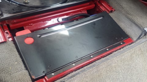
After two days I collected my van and was really happy with the work he had done fitting the leisure battery. As an added bonus he had managed to route the cable from controller to starter battery. This is the leisure battery. As you can see it’s snug but not not too obvious when the compartment door is closed.
BatteryDoor only slightly proudDoor only slightly proud
Here you can see where the black cable for the starter battery enters the wardrobe (right) , and feeds through a hole he drilled in the floor, which in turn is fed into the engine bay and round to the battery. The hole was sikaflexed to stop water ingress.
Routing of cable in wardrobe from solar controller to battery
Below you can see that the LED solar display is now showing two batteries connected and the red error / warning light has gone out 🙂
Well that’s pretty much my solar install from start to finish. I hope this has been useful and if anybody needs any more information please leave a comment and i will message back accordingly 🙂
Andy
*Amendment
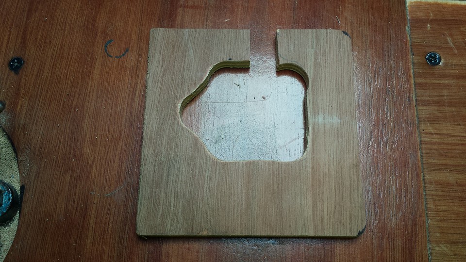
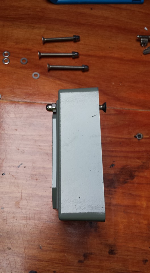
Although the LCD controller appeared to stick to the units like glue with the foam sticky pads, I think the change in temperature on hot days \ cool nights was enough to upset it enough and it kept coming away leaving it hanging from the data cable. I realized that the surface area of the small foam pads on the thin outer edge of the display molding wasn’t enough to keep it in place. This got really frustrating so i set to concocting a more permanent fix. This consisted of a piece of ply board cut to shape and painted grey to match the interior of the van.
Cut Ply BoardPainted Grey
Four holes were drilled in the board to match up with the holes in the LCD display unit. I brought 4 stainless countersunk head screws which were fed in from the bach of the ply board, through the display and tightened up. The strange shape hole cut in the ply allowed the data cable to feed out of the back. The controller has a much greater contact area at the rear of the display for double sided adhesive tape, and as a result has stayed firmly in place since mounted. Result 🙂
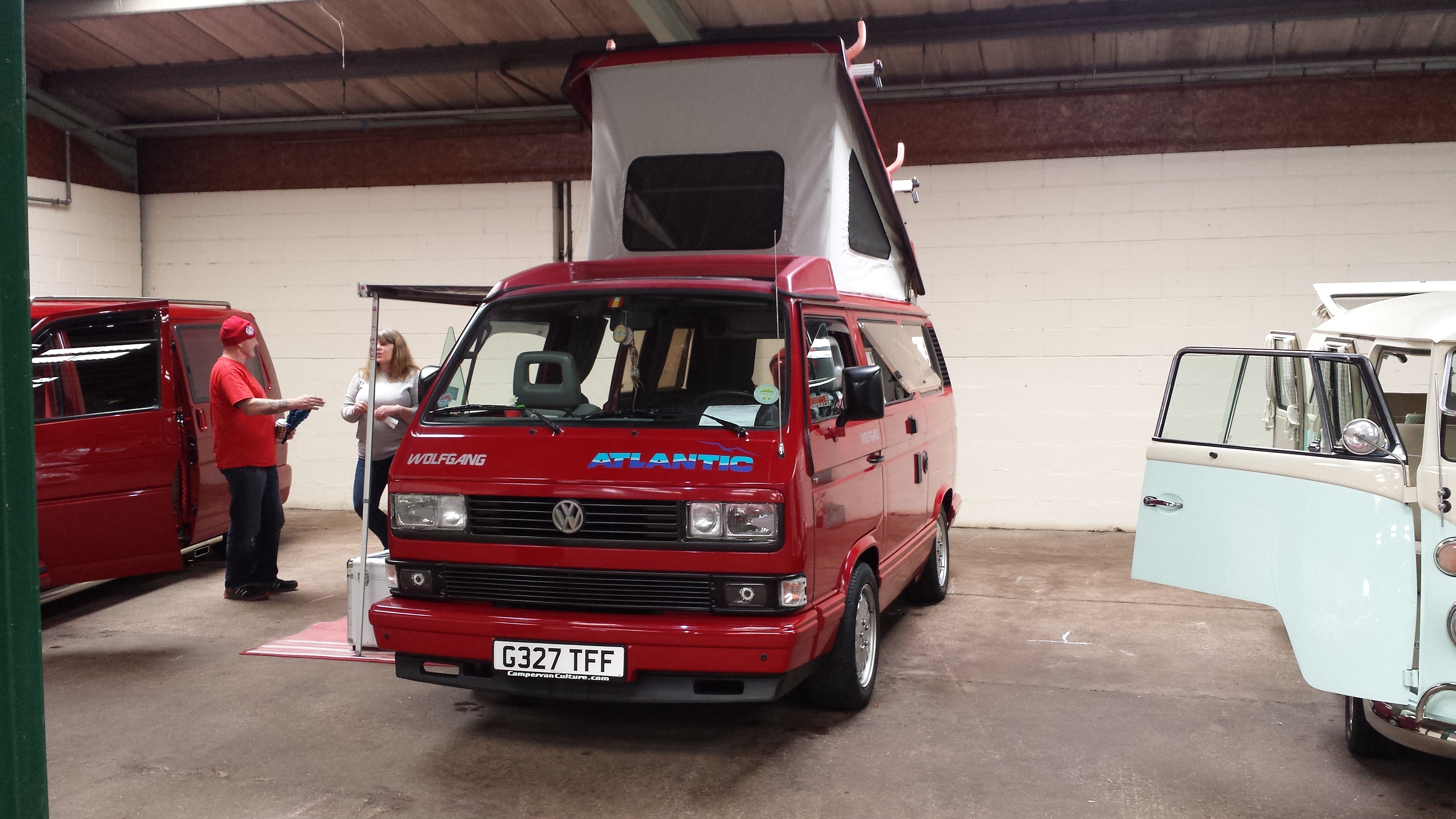
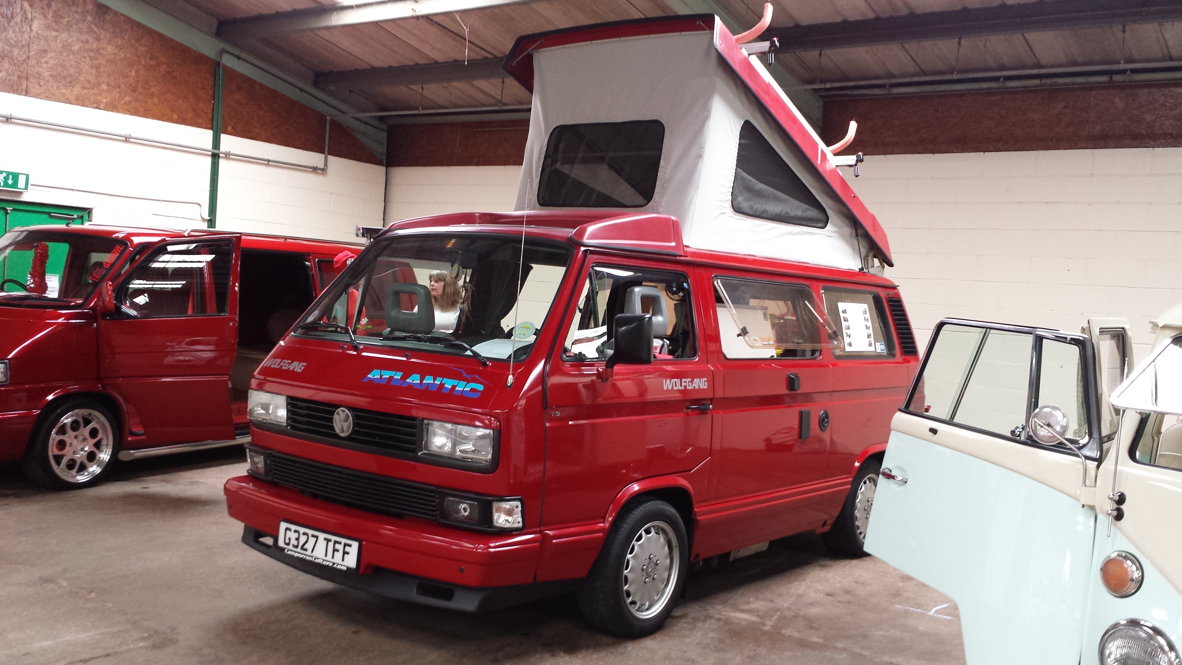
Last year Mandy and Myself attended Dubfeeze 2015 as invited members or Volkswagen Owners Club. It was great fun, but I was really disappointed that there wasn’t a T3 / T25 represented in the ‘Show n Shine’. Every other type of VW was present (Split screen campers, Bay window campers, Beetles, Golfs, Polo’s etc, etc). So this year I made a point of applying for a spot in the Show n Shine. It was great to get accepted, and Wolfgang was well received and had plenty of attention.
YouTube video below courtesy of good friend Jon Payne . Wolfgang has a guest appearance towards the end 🙂